Atkinson Dynamics AD-28LD-MV Guía rápida

INSTALLATION AND SERVICE INSTRUCTIONS
MODEL AD-28LD-MV
CALL
WARNING: DISCONNECT POWER BEFORE REMOVING COVER
TALK
LISTEN
290A3077B
2562445A
REV. A 1108
Printed in U.S.A.
UNIVERSITY PARK, IL USA

-2-
INSTALLATION AND SERVICE INSTRUCTIONS
FOR
MODEL AD-28LD-MV
SAFETY MESSAGE TO INSTALLERS, USERS AND
MAINTENANCE PERSONNEL
It is important to follow all instructions shipped with this prod-
uct. This device is to be installed by a trained electrician who is
thoroughly familiar with the National Electrical Code and will follow
NEC Guidelines as well as local codes.
The selection of the mounting location for the device, its controls
and the routing of the wiring is to be accomplished under the direc-
tion of the facilities engineer and the safety engineer. In addition,
listed below are some other important safety instructions and precau-
tions you should follow:
• ThisisnotaListedsafetydeviceandisnotintendedtobe
used as such.
• Readandunderstandallinstructionsbeforeinstallingor
operating this equipment.
• Disconnectpowerbeforeconnectingordoinganymainte-
nance on this intercom.
• Alleffectivewarningspeakersproduceloudsoundswhich
may cause in certain situations, permanent hearing loss.
Youshouldtakeappropriateprecautionssuchaswearing
hearing protection.
• Aftertestingiscomplete,provideacopyofthisinstruction
sheet to all operating personnel.
• Establishaproceduretoroutinelychecktheintercom
installationforintegrityandproperoperation.Anymain-
tenance must be performed by a trained electrician in
accordance with NEC guidelines and local codes.
Failure to follow all safety precautions and instructions may re-
sult in property damage, serious injury, or death to you or others.

Figure 1.
-3-
A. GENERAL FEATURES.
TheAD-28LD-MVintercomisa2-waycommunicationsdevice
designed for light duty industrial applications. Nominal operating
voltagesinclude120/240Vac,50/60Hzand24Vdc.Voltagechanges
forthe120/240VACareinternallyswitchselectableandtheACline
isfusedwitha1/2amp250volttypeGMCfuse.Theunitalsooffers
internally selectable balanced or unbalanced line operation, trans-
formerisolatedaudioinputsandinternallyselectableMasterorSlave
modecongurations.Acallbuttonwithremotecalldrycontactsis
alsofactorysuppliedintheunit.TheAD-28LD-MVhasaType1en-
closureandisaULListedsignalappliance.
MASTERMODE:
EachintercomcanbeconguredasaMasterunit(Push-to-Talk)
oraSlaveunit(Push-to-Listen)bychangingtheMAS/SLAjumper
(J3)ontheprintedcircuitboard(seegure1).Theintercomcomes
fromthefactorysetintheMaster(MAS)mode.
IntheMastermodetheintercomactsasanamplier,constantly
broadcastingoveritsspeakeranysignalthatitreceivesonthesignal
lines.HoldingdowntheListen/Talkswitchchangestheunitfroma
speakertoamicrophone(seegure2).Theintercomwillnowtrans-
mitoverthesignallinestoadditionalintercom(s)alsosetinthe
R6
C11
REPLACE
CM
TYPE
J2
240VAC
ONLY
SAME
SW1
FUSE
WITH
GMC-1/2
1/2A
CR1
+
J1
T3
120VAC
1
C2
C1
R1
CR2
P
K1
C5 C9
C4 C8
C7
R18 24VDC
CALL
IN/OUT
CONTROL
GROUND
CONTACT
SPEAKER
2001290 A
K2
R19
EXT
REMOTE
REMOTE
-
+
IC3
C21
T2
CR7
CR6
CR5
CR4
C13
J4
>BAL
>UNB
J5 R17
R16
Q3
CR3
R15
C14
>MAS
>SLA
J3
R12
R13
R14
S
J6
R11
R10
R3
R2
C10
Q2
R8
R9
R7
C20
C19
C18
C17
R34
J7
C22 O
CR8
R33
R31
R32
R30
R29
R28
R27
R26
R25
R21
R22
R24
R23
T1
C3 C6
Q1 IC1
C12 R5
R4
C16
IC2
C15
R20
V
L
W
I
T
C
H
S
K
R
250V
F1
H1
H2
TO SPEAKER
FUSE
CLASS I WIRING
120VAC/240VAC
SWITCH
TO SWITCH
MASTER/SLAVE
JUMPER
VOLUME
CONTROL
CLASS II WIRING
BAL/UNBAL
JUMPER(2)
290A3076

-4-
Figure 2.
mastermode.Whentheswitchisreleaseditwilldefaultbacktothe
ListenorSpeakermode,allowingtheusertoreceiveanymessages
transmittedbacktoit.Theoutputamplieroffersfullshortcircuit
protection and over heat protection.
SLAVEMODE:
Someapplicationsmayrequirethattheintercomconstantly
transmit(i.e.,actasamicrophone)asopposedtoconstantlyreceive
(i.e.,actasaspeaker).Toaccomplishthistheintercommustbe
switchedintotheSlave(Push-to-Listen)mode.
WARNING
Disconnectpowertotheintercombeforeanyinstallation,
maintenance, or configuration changes are performed.
MovetheJ3jumperblockontheP.C.boardfromtheMAStoSLA
position(seegure1).Thiscanbedoneusinglongnosepliers,pull-
ingtheblockoffthe“MAS”andcenterpositionandplacingitonthe
“SLA”andcenterposition.
WhenhookedtoaMasterunititmaybenecessarytooverride
theSlaveunitinorderfortheMasterunittobeabletotransmit.The
remotecontrolandgroundlinesmustbeconnectedbetweentheMas-
terandtheSlaveunit.ParagraphG.WIRINGDIAGRAMScontains
wiring diagrams of typical intercom configurations.
CALL
WARNING: DISCONNECT POWER BEFORE REMOVING COVER
TALK
LISTEN
290A3077B
UNIVERSITY PARK, IL USA

-5-
REMOTECONTROL:
Remotecontrolisusedtochangetheoperationmodeofaremote
intercomfromlistentotalkorfromtalktolistenuponactivationof
alocalintercom.ThewiringdiagramsectionillustratesMaster/Slave
InstallationandUsingFootSwitchesDiagrams.(Seegures5and6.)
NormallyopenfootswitchescanalsobeconnectedtotheRemote
Controllineandgroundinordertoallow“handsfree”operationofthe
listen/talkfunctions.
CALLBUTTONANDCALLDRYCONTACTSTOEXTERNALDE-
VICE:
Depressingthecallbuttonsendsa1kHztoneontothesignal
lines.Allunitslisteningtothelinewillthenbroadcastthissignalas
acall.Depressingthecallbuttonalsoclosesanormallyopendrycon-
tactratedat0.4amps@125Vacor1.25amps@24Vdc.Thiscontact
can be used to trigger a remote sounder or light in order to accent the
call feature. The wiring diagram illustrates how an external light or
horncanbewiredintoaugmentthecalltone.(Seegure7.)
CAUTION
The call signal is substantially louder than normal voice mes-
sagesbeingcarriedontheline.Donotdepressthecallswitch
while carrying on a conversation with someone on the system.
This will subject the listener to very loud sound levels.
24Vdc:
TheAD-28LD-MViscapableofsendingDCpowertoanotherunit
thatismountedinaremotelocationwithoutlocalpower.24Vdcis
availablefrompositions6and7ofterminalblockJ7.Itcanberun
alongwiththesignallinestoanintercominaremotelocation.Only
one unit should share the power supply of another unit in any instal-
lation.Figure8inthewiringdiagramssectionshowshowtwointer-
comscanbehookedupifnoremotepowerisavailable.
CAUTION
Ifanintercomisintendedtoberunoffofaseparate24Vdc
supply,theoutputmustbelimitedto24Vdc,760mAoutput.
-6-
Figure 3.
ISOLATEDBALANCED/UNBALANCEDLINES:
The audio signals are transmitted over a wire pair using balanced
line technology. This means each wire carries a signal that is opposite
inpolarityoftheother.Attheinputoftheintercomisanisolated
balanced line transformer. This transformer subtracts the two signals
from each other providing an output free of noise generated onto the
wires by some other noise source such as a motor or light fixture near
the wires.
The isolation provided by the transformer means that the grounds
of the units are not connected by the audio lines. Therefore, ground
loops and other problems caused by non-isolated systems are avoided.
The polarity of the audio lines between the + and - signal terminals
need not be maintained.
Ashieldedcablecanbeusedininstallationswhereextreme
problems from interference are suspected. The shield should always
be connected to the ground of only one of the intercoms. Connecting
the shield to ground at both ends will cause ground currents to travel
through the shield which could cause hum in the system.
Thereareseveraldiagramsinthebackofthemanualtoaidin
wiring intercoms together. The wiring diagram section illustrates bal-
anced and unbalanced line interconnection along with how a shielded
audiocablecanbeused.(Seegures5through12.)Italsoillustrates
290A3078
24VDC IN/OUT
GROUND
GROUND
CLASS I WIRING CLASS II WIRING
REMOTE CONTROL
REMOTE SPEAKER
EXT CALL
CONTACT
+
-
COMMON
J2
J7
PHASE

-7-
multiple intercom interconnections.
MODELAD-28LD-MV
SPECIFICATIONS
OperatingVoltage24Vdc,120Vacand240Vac50/60Hz
CurrentDraw Voltage Operating Standby
24Vdc 120mA 60mA
120Vac 80mA 60mA
240Vac 40mA 30mA
CAUTION:The24Vdcinputmustbelimitedto760mAoutifrun
from a supply.
AmplierSpecications
FrequencyResponse(–6dB)150Hzto12kHz
InputImpedance 3400ohms
Max.OutputVoltage
SineWave:
BalancedOutput 15Vrms
UnbalancedOutput 7.5Vrms
SquareWave:
BalancedOutput 19Vrms
UnbalancedOutput 9.5Vrms
SpeakerRating 2watts
SpeakerImpedance 8ohm
TemperatureRange −31°Fto+150°F
(–35°Cto+66°C)
FuseTypeGMC-1/2 1/2A,250V
CallSwitchContactRating 400mA@125Vac
1.25A@24Vdc
AgencyApprovals UL,Type1
Weight
Shipping 3lb,9oz
Net 3lb,2oz
HousingDimensions 6.87"Wx8.00"Hx3.05"D
ConduitEntrances Dual1/2"-3/4"Knockouts
HousingMaterial Aluminum
Color Black

-8-
B. UNPACKING.
AfterunpackingtheModelAD-28LD-MV,examineitfordamage
that may have occurred in transit. If the equipment has been dam-
aged, do not attempt to install or operate it, file a claim immediately
withthecarrierstatingtheextentofthedamage.Carefullycheckall
envelopes, shipping labels and tags before removing or destroying
them.
Beforeattemptingtoinstalltheintercom,besurethatallparts
listedintheKITCONTENTSLISThavebeensupplied.
C. KIT CONTENTS LIST.
Qty. Description Part Number
1 InstructionManual 2562445
1 Resistor,1K,1W K101216
D. MOUNTING.
CAUTION
The selection of the mounting location for the device, its con-
trols and the routing of the wiring is to be accomplished under
the direction of the facilities and the safety engineer.
The intercom is intended to be mounted on any relatively flat and
rigid surface by the four mounting holes in the interior of the housing.
Figure4isadimensionaloutlinedrawingshowingthepropermount-
ingconguration.Thefourmountingholesare0.202indiameterand
aredesignedtoaccepta#10mountingscrew.Hardwareformounting
the intercom to the surface is left up to the installer. The intercom
housinghastwocombination1/2"-3/4"knockoutsinthebottom.When
installingtheconduittotheseopenings,choosingthesizeandtypeof
connector is left up to the installer.
E. ELECTRICAL CONNECTIONS.
WARNING
Donotconnectwireswhenpowerisapplied.
The intercom has two wiring compartments, one for Class I wir-
ingandthesecondforClassIIwiring.Allwiringtotheintercomis
terminatedattwopcboardmountedterminalblocksprovided.The
ACPhaseandCommon,alongwithEarthGround,arelandedina

-9-
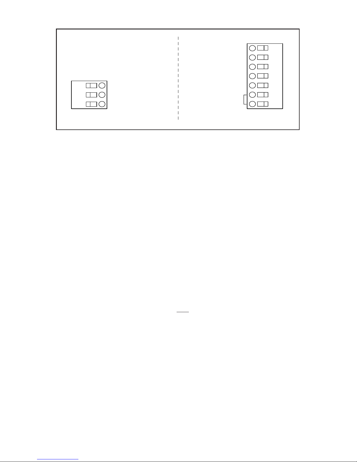
three-positionterminalblock(J2)intheClassIwiringcompartment.
The signal lines, remote control lines, remote power, and call dry con-
tactsarelandedinaseven-positionterminalblock(J7)intheClassII
wiring compartment. The two wiring sections are isolated by a fishpa-
per barrier.
WARNING
Disconnectpowertotheintercombeforeanyinstallation,
maintenance, or configuration changes are performed.
TherearethreejumpersshownonthePCboardinFigure7that
may need to be moved depending on the desired operation of the
intercom.J4andJ5areforoperatingtheintercomineitherabal-
anced signal line or unbalanced signal line configuration. These must
be moved together as a pair. They are factory set in the balanced line
position.J3isforconguringtheintercomaseitheramasterorslave
device. The intercom is factory set in the master position.
There is a switch on the board, in the Class I wiring compart-
ment,toconguretheoperationoftheboardfrom120Vacto240Vac.
Theswitchisfactorysetfortheintercomtooperateon120Vac(see
gure3).
Seegures5through12fortypicalintercomcongurations.
F. SERVICE.
CAUTION
Anymaintenancemustbeperformedbyatrainedelectrician
in accordance with NEC guidelines and local codes.
1. General.
CAUTION
The call signal is substantially louder than normal voice mes-
sagesbeingcarriedontheline.Donotdepressthecallswitch
while carrying on a conversation with someone on the system.
This will subject the listener to very loud sound levels.
FederalSignalwillserviceyourequipmentorprovidetechni-
cal assistance with any problems that cannot be handled locally.
AnyunitsreturnedtoFederalSignalforservice,inspection,or
repairmustbeaccompaniedbyaReturnMaterialAuthorization.
ThisR.M.AcanbeobtainedfromthelocalDistributororManufac-
turer’sRepresentative.

Figure 4.
-10-
Atthistimeabriefexplanationoftheservicerequestedorthe
nature of the malfunction, should be given.
Addressallcommunicationsandshipmentsto:
ServiceDept.
AtkinsonDynamics
FederalSignalCorp.
2645FederalSignalDr.
UniversityPark,IL60466-3195
2. Replacement Parts.
WARNING
ReplacefusewithGMC-1/2only.DONOTsubstitute.
Description PartNumber
Resistor,1K,1W K101216
Fuse,GMC-1/2 K148A155
Mini-jumpers K139A209
PCBA K2001290
Switch K122283
Speaker K132141
8.00
FRONT BACK
BOTTOM
CLASS I WIRE
ENTRY
CLASS II WIRE ENTRY
6.87
3.50
COMBINATION 1/2"-3/4" KNOCK-OUT
3.05
1.40
7.125
5.50
290A3079B
4 x .202
CALL
WARNING: DISCONNECT POWER BEFORE REMOVING COVER
TALK
LISTEN
UNIVERSITY PARK, IL USA
Tabla de contenidos
Otros manuales de Sistema de intercomunicación de Atkinson Dynamics


