Aquagem IP20 Manual de usuario


THANK YOU FOR PURCHASING OUR INVERTER POOL PUMPS.
THIS MANUAL CONTAINS IMPORTANT INFORMATION THAT WILL HELP YOU IN OPERATING
AND MAINTAINING THIS PRODUCT.
PLEASE READ THE MANUAL CAREFULLY BEFORE INSTALLATION & OPERATION AND RETAIN
IT FOR FUTURE REFERENCE.
CONTENTS
1. IMPORTANT SAFETY INSTRUCTIONS.......................................................................................................................... 1
2. TECHNICAL SPECIFICATIONS....................................................................................................................................................... 2
3. OVERALL DIMENSION (mm)........................................................................................................................................................ 2
4. INSTALLATION................................................................................................................................................................................... 3
5. SETTING AND OPERATION........................................................................................................................................................... 5
6. WIFI OPERATION............................................................................................................................................................................13
7. EXTERNAL CONTROL....................................................................................................................................................................20
8. PROTECTION AND FAILURE .......................................................................................................................................................21
9. MAINTENANCE...............................................................................................................................................................................23
10. WARRANTY& EXCLUSIONS .....................................................................................................................................................24
11. DISPOSAL .......................................................................................................................................................................................24

1
1. IMPORTANT SAFETY INSTRUCTIONS
This guide provides installation and operation instructions for this pump. If you have any other questions
about this equipment, please consult your supplier.
1.1 When installing and using this electrical equipment, basic safety precautions should always be
followed, including the following:
•RISK OF ELECTRICAL SHOCK. Connect only to a branch circuit protected by a ground-fault
circuit-interrupter (GFCI). Contact a professionally trained and qualified electrician if you cannot verify that
the circuit is protected by a GFCI.
•TO PREVENT THE RISK OF ELECTRICAL SHOCK, please connect the ground wire on the motor
(green/yellow) to the grounding system.
•This pump is for use with permanently installed in-ground or above-ground swimming pools and may
also be used with hot tubs and spas with a water temperature under 50℃. Due to the fixed installation
method, this pump is not suggested to be used on above-ground pools that can be readily disassembled
for storage.
•The pump is not submersible.
•Never open the inside of the drive motor enclosure.
1.2 All installations must be fitted with earth leakage or residual current protection devices, having a
rated residual operating current not exceeding 30mA.
WARNING:
•Fill the pump with water before starting. Do not run the pump dry. In case of dry run, mechanical seal
will be damaged and the pump will start leaking.
•Before servicing the pump, switch OFF power to the pump by disconnecting the main circuit to the
pump and release all pressure from pump and piping system.
•Never tighten or loosen screws while the pump is operating.
•Ensure that the inlet and outlet of the pump are unblocked with foreign matter.

2
2. TECHNICAL SPECIFICATIONS
3. OVERALL DIMENSION (mm)
Model
Advised
Pool
Volume
(m³)
P1
Voltage
(V/Hz)
Qmax
(m³/h)
Hmax
(m)
Circulation (m³/h)
KW
At 8m
At 10m
IP20
30-50
0.75
220-240/
50/60
24.0
18.0
19.0
15.0
IP25
40-70
1.05
27.0
20.0
24.5
21.0
IP30
60-90
1.4
29.5
21.0
29.5
26.5
IP40
80-120
1.75
42.0
21.0
38.0
34.0
Figure 1

3
4. INSTALLATION
4.1. Pump Location
1) Install the pump as close to the pool as possible, to reduce friction loss and improve efficiency, use short,
direct suction and return piping.
2) To avoid direct sunshine, heat or rain, it is recommended to place the pump indoors or in the shade.
3) DO NOT install the pump in a damp or non-ventilated location. Keep pump and motor at least 150mm
away from obstacles, pump motors require free circulation of air for cooling.
4) The pump should be installed horizontally and fixed in the hole on the support with screws to prevent
unnecessary noise and vibration.
4.2. Piping
1) For optimization of the pool plumbing, it is recommended to use a pipe with size of 63mm. When
installing the inlet and outlet fittings (joints), use the special sealant for PVC material.
2) The dimension of suction line should be the same or larger than the inlet line diameter, to avoid pump
sucking air, which will affect the efficiency of the pump.
3) Plumbing on the suction side of the pump should be as short as possible.
4) For most installations we recommend installing a valve on both the pump suction and return lines,
which is more convenient for routine maintenance. However, we also recommend that a valve, elbow, or
tee installed on the suction line should be no closer to the front of the pump than seven times the suction
line diameter.
5) Pump outlet piping system should be equipped with a check valve to prevent the pump from the impact
of medium recirculation and pump-stopping water hammer.

4
4.3. Valves and Fittings
1) Elbows should be no closer than 350mm to the inlet. Do not install 90°elbows directly into the pump
inlet/outlet. Joints must be tight.
* The pump inlet/outlet union size: optional with 48.5/50/60.3/63mm
2) Flooded suction systems should have gate valves installed on suction and return line for maintenance;
however, the suction gate valve should be no closer than seven times the suction pipe diameter as
described in this section.
3) Use a check valve in the return line where there is a significant height between the return line and the
outlet of the pump.
4) Be sure to install check valves when plumbing in parallel with other pumps. This helps prevent reverse
rotation of the impeller and motor.
4.4 Check before initial startup
1) Check whether pump shaft rotates freely;
2) Check whether power supply voltage and frequency conform to the nameplate;
3) Facing the fan blade, the direction of motor rotation should be clockwise;
4) It is forbidden to run the pump without water.
Return to pool 63mm
Elbow
Suction 63mm
350mm
Figure 2

5
4.5 Application conditions
Ambient temperature
Indoor installation, temperature range: -10 - 42℃
Water temperature
5℃-50℃
Salt pools
Salt concentration up to 0.5%, i.e 5g/l
Humidity
≤90% RH, (20℃±2℃)
Installation
The pump can be installed max. 2m above water level;
Insulation
Class F, IP55
5. SETTING AND OPERATION
5.1 Display on control panel:
①Power consumption
②Running capacity / Flow rate
③WIFI indicator
④Unit of flow
⑤Timer period
⑥Timer 1/2/3/4
Backwash/unlock
Up/down: to change the value
(capacity/flow/time)
Switch between Manual-Inverter Mode and
Auto-Inverter Mode
Manual-Inverter Mode: The running capacity will be
set manually between 30%-120%
Auto-Inverter Mode: The running capacity will be
automatically adjusted between 30%-120% according
to the preset flow rate.
The default mode is Manual-Inverter mode.
Timer setting
On/off

6
5.2 Startup:
When the power is switched on, the screen will fully light up for 3 seconds, the device code will be
displayed, and then it will enter the normal working state. When the screen is locked, only the button
will light up; Press and hold for more than 3 seconds to unlock the screen. The screen will
automatically lock up when there is no operation for more than 1 minute and the brightness of the screen
will be reduced to 1/3 of the normal display. Short press to wake up the screen and observe the
relevant operating parameters.
5.3 Self-priming
When switched on for the first time after installation, the pump will start self-priming.
When the pump performs self-priming, it will count down from 1500s and stop automatically when the
system detects the pump is full of water, then the system will recheck for 30s again to make sure the
self-priming is completed.
User can exit self-priming manually by pressing for more than 3 seconds. The pump will enter the
default Manual-Inverter mode at the initial startup. If the user exits the self-priming in the subsequent
startup, the pump will return to the previous state before the last shutdown.
Remark:
The pump is delivered with self-priming enabled. Each time the pump restarts, it will perform self-priming
automatically. User can enter the parameter setting to disable the default self-priming function (see 5.10)
If the default self-priming function is disabled, and the pump has not been used for a long time, the water
level in the strainer basket may drop. User can manually activate the self-priming function by pressing
both for 3 seconds, the adjustable period is from 600s to 1500s (default value is 600s). After
the manual self-priming is completed, the pump will return to the previous state before activating the
manual self-priming. If the pump has entered the Auto-Inverter mode previously, the pump will perform
self-learning for 180s to redefine the adjustable flow range after the manual self-priming.
User can press for more than 3 seconds to exit the manual self-priming, and the pump will run the
same as the manual self-priming is completed.

7
5.4 Backwash
User can start the backwash or fast re-circulation in any running state by pressing .
Default
Setting range
Time
180s
Press or to adjust from 0 to 1500s with 30
seconds for each step
Running capacity
100%
80-120%, enter the parameter setting (see 5.10)
Exit backwash:
When backwash mode is on, user can hold for 3 seconds to exit, the pump will return to the
previous state before backwash. If a speed limit is set by the user, the running capacity of the backwash will
not exceed the set speed limit. (see 5.9)
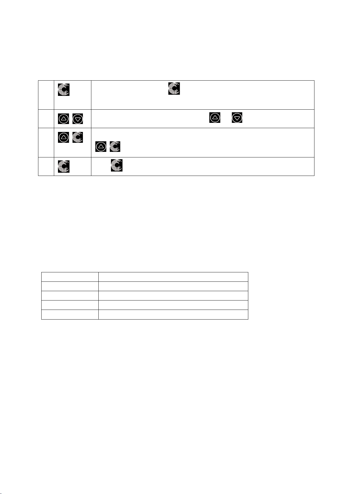
5.5 Manual-Inverter Mode
1
Hold for more than 3 seconds to unlock the screen;
2
Press to start. The pump will run at 80% of the running capacity at the
initial startup after the self-priming.
3
Press or to set the running capacity between 30%-120%, each
step by 5%
4
Press again to switch to Auto-Inverter mode.
Note:
When the pipeline pressure is too high, to maintain an adequate flow rate, user can set the running
capacity to 105%-120%. The pump will run at a higher speed but will not exceed the rated power of
each model. If the pump has reached the rated power at 105% and the user continues to increase
the running capacity, the display will return to 105% when the motor speed is stabilized.

8
5.6 Auto-Inverter Mode
Under Auto Inverter Mode, the pump can automatically detect the system pressure and adjust the speed
of motor to reach the set flow.
1
Unlock the screen, press to switch from the Manual-Inverter mode to
Auto-Inverter mode.
2
The flow rate could be adjusted, by pressing or with 1m³/h for each step.
3
The unit of flow rate could be changed to LPM, IMP GPM or US GPM, by pressing both
for 3 seconds
4
Press to switch to Manual-Inverter mode
Self-learning:
When first switching to the Auto-Inverter mode manually or via external control or activating timer mode
with flow rate setting, the system will perform the self-priming process (see 5.3) and then the self-learning
process for 180s and redefine the adjustable flow range of the pump by detecting the pipeline pressure.
eg: the default adjustable flow range of InverPro IP25 is 5-25 m³/h, after self-learning, the range may be
redefined to 7-22 m³/h. If the set flow is beyond the current adjustable range, the actual achievable flow
rate will be displayed after the motor speed is stabilized.
The default adjustable flow range for InverPro is as below:
Model
Default adjustable flow rate range
IP20
5-20 m³/h
IP25
5-25 m³/h
IP30
5-30m³/h
IP40
8-35m³/h
Note:
After the first self-priming, the pump will redefine the adjustable flow range. The pipeline pressure will be
recorded by the system after the pump runs at the set flow/capacity for 5 minutes without other
operations.
During the pump running, if it is detected that the pipeline pressure changes beyond a certain range, the
icon of % or m³/h (or other flow units) symbol will flash for 5 minutes. If the change last for 5 minutes, the
pump will perform a self-priming and self-learning process, and redefine the flow range accordingly.
After the redefinition of the flow range, the pump will automatically adjust the running capacity to reach
the set flow.
User can set the time interval to trigger the self-leaning automatically in the parameter setting (see 5.10)
to ensure the accuracy of the flow rate.
Este manual sirve para los siguientes modelos
3
Tabla de contenidos
Otros manuales de Bomba de piscina de Aquagem
Manuales populares de Bomba de piscina de otras marcas

Resol
Resol DeltaSol B Pro Manual de usuario

Evolution Aqua
Evolution Aqua UniTech Perfect 5000 Manual de usuario

Outside Living Industries
Outside Living Industries Ubbink Heatermax Pool Guía de inicio rápido

CPI
CPI Olympic 2P1815 Manual de usuario

Flotec
Flotec FP6121-01 Manual de usuario

Pentair
Pentair ONGA LEISURETIME LTP400 Manual de usuario