Apator ARS 00/100 Manual de usuario

Apator S.A., 87-100 Toru ul. Gda ska 4a lok. C4
tel.: +48 56 61 91 , fax: +48 56 61 91 295
www.apator.com
Zak ad produkcyjny
Ostaszewo 57C, 87-148 ysomice
ń, ń
353
ł
Ł
Manufacturing area
ARS 00/100
Instrukcja obsługi i montażu listwowych
rozłączników izolacyjnych ARS 00/100 mm
Mounting and operation manual of ARS 00/100 mm
vertical fuse switch disconnectors
Opis montażu
Mounting
ISO 9001:2000 ISO 14001
PN-N-18001

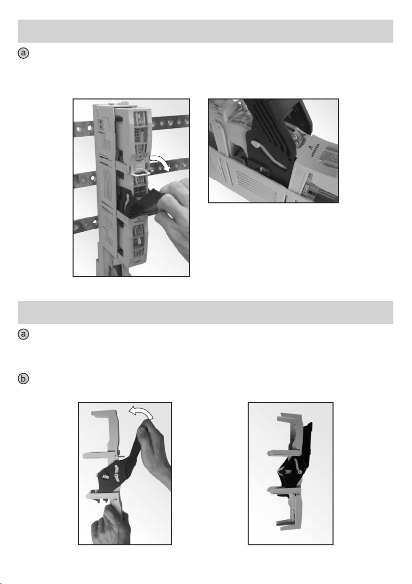
1. ZDJĘCIE POKRYWY ROZŁĄCZNIKA
TAKING OFF THE COVER OF DISCONNECTOR
Chwycić za rączkę (Fot. 1) i przemieścić ją w pozycję (Fot. 2), tzn. dźwignia rączki
zablokowana o występ pokrywy (Fot. 2a).
Take a handle (Fig. 1) and move to position (Fig. 2), until the lever for a handle is locked by the
ledge of the cover (Fig.2a).
Fot. 1
Fot. 2a
Fot. 2
Przesunąć element zwalniający blokadę (Fot. 3) zgodnie z kierunkiem pokazanym przez
strzałkę umieszczoną na zwalniaczu blokady w położenie skrajne (Fot. 4)
Move the element releasing the interlocking (Fig. 3) to an extreme position according to
direction indicated by the arrow located on the release of interlocking (Fig. 4).
Fot. 3 Fot. 4

Zdjąć pokrywę.
Take off the cover.
Fot. 5
2. OTWORZENIE PŁYTEK MASKUJĄCYCH ŚRUBY MOCUJĄCE.
ZAMOCOWANIE ROZŁĄCZNIKA ARS 00/100 mm DO SZYN ZBIORCZYCH.
ZAMKNIECIE PŁYTEK MASKUJĄCYCH ŚRUBY MOCUJĄCE.
OPENING THE MASKING PLATES FOR FIXING BOLTS. MOUNTING OF ARS
00/100 mm TYPE DISCONNECTOR ON BUS BURS. CLOSING OF MASKING
PLATES FOR FIXIG BOLTS.
Otworzyć płytki maskujące śruby mocujące (Fot. 6 i 6a).
Open the masking plates for fixing bolts (Fig. 6 and 6a).
Fot. 6
Fot. 6a

Przyłożyć podstawę rozłącznika do szyn zbiorczych o rozstawie 100mm, wkręcić śrubę w
środkowym biegunie (Fot. 7), a następnie wkręcić śruby w pozostałych biegunach. Śruby dokręcać
momentem od 8÷10 Nm. Po zamocowaniu rozłącznika do szyn zbiorczych zamknąć płytki
maskujące (Fot. 8).
Put the base of disconnector against bus bars with spacing of 100 mm, screw in a bolt in the
middle pole (Fig. 7) and then screw in bolts in remaining poles. Screw in the bolts with the torque of
8 10 Nm. Close the masking plates after the disconnector is mounted on the bus bars (Fig. 8).÷
Fot. 7 Fot. 8
3. ZDJĘCIE OSŁONY ZACISKÓW I PRZYMOCOWANIE PRZEWODÓW
ODPŁYWOWYCH (Fot. 9 i Fot. 10a, Fot. 10b)
TAKING OFF THE SHIELD FOR TERMINALS AND FIXING OF OUTLET CABLES
(Fig. 9 and Fig. 10a, Fig. 10b)
Zdjąć osłonę zacisków (Fot. 9) i dokręcić przewody odpływowe (Fot. 10a, Fot. 10b).
Take off the shield for terminals (Fig. 9) and screw in outlet cables (Fig. 10a, Fig10b).
Fot. 9
Fot. 10a Fot. 10b

4. ZAKŁADANIE DODATKOWYCH ELEMENTÓW OPISOWYCH W OSŁONIE
ZACISKÓW (Fot. 11) ORAZ POD SZYBKAMI (Fot. 12)
MOUNTING OF ADDITIONAL DESCRIPTION ELEMENTS ON THE SHIELD FOR
TERMINALS (Fig. 11) AND UNDER SIGHT-GLASSES (Fig. 12)
Fot. 11 Fot. 12
5. MONTOWANIE WKŁADEK TOPIKOWYCH W POKRYWIE (Fot. 13), ZAŁOŻENIE
OSŁONY ZACISKÓW (Fot. 14)
MOUNTING OF FUSE LINKS ON THE COVER (Fig. 13), TAKING ON THE
SHIELD FOR TERMINALS (Fig. 14)
Fot. 13
Fot. 14

6. UMIESZCZANIE POKRYWY Z ZAMONTOWANYMI WKŁADKAMI TOPIKOWYMI
W OBUDOWIE ROZŁĄCZNIKA
PUTTING THE COVER WITH THE FUSE LINKS IN THE CASING OF THE
DISCONNECTOR
Przemieścić rączkę w skrajne położenie tzn. dźwignia rączki otwarta i zablokowana o występy
pokrywy. Umieścić pokrywę w prowadnicach znajdujących się w obudowie (Fot. 15) zwracając uwagę
na prawidłowe umiejscowienie prowadnic po obu stronach rozłącznika (Fot. 15a, 15b).
Move a handle to an extreme position until the lever of the handle is open and locked by the ledge
of the cover. Put the cover in the guidelines of the casing (Fig. 15) taking into account the correct placing
of guidelines on both sides of the disconnector (Fig. 15a, 15b).
Fot. 15 Fot. 15bFot. 15a
7. ZAŁĄCZANIE APARATU
SWITCHING ON THE APPARATUS
Chwycić rączkę i energicznym ruchem przesunąć ją w kierunku
jak wskazuje strzałka aż do całkowitego zamknięcia pokrywy (Fot. 16).
Take the handle and firmly move according to direction indicated
by the arrow until the cover is completely closed (Fig. 16).
Fot. 16
8. ROZŁĄCZANIE APARATU
SWITCHING OFF THE APPARATUS
Chwycić za rączkę rozłącznika i wykonać energiczny ruch rączką w kierunku zgodnym ze strzałką
(Fot. 17), aż do momentu, gdy rączka zostanie zablokowana o występ pokrywy (Fot. 17a).
Take a handle of the disconnector and move firmly in direction indicated by the arrow (Fig. 17), until
the handle is locked by the ledge of the cover (Fig.17a).
Fot. 17a
Fot. 17
9. PARKOWANIE I ZWOLNIENIE STANU PARKOWANIA APARATU
PARKING AND RELEASING OF PARKING OF THE APPARATUS
Rozłączyć aparat zgodnie z punktem 8 instrukcji, następnie postępować według punktu 1b oraz 1c
instrukcji.
Disconnect the apparatus in accordance with the point 8 of the manual and then proceed
according to the points 1b and 1c of the manual.
Zamknąć rączkę zgodnie z kierunkiem strzałki (Fot. 18).
Close a handle according to direction indicated by the arrow (Fig. 18).
Fot. 18 Fot. 18a

W celu zaparkowania, pokrywę z zamkniętą rączką (Fot. 18a) wsunąć w prowadnice w
obudowie (Fot. 19), zwracając uwagę na prawidłowe umiejscowienie prowadnic po obu stronach
rozłącznika (Fot. 19a i 19b), aż do momentu uzyskania oporu oznaczającego unieruchomienie
pokrywy.
In order to park, insert the cover with a handle closed (Fig. 18a) into guidelines of the casing
(Fig. 19), taking into account the placing of the guidelines on both sides of the disconnector (Fig.
19a and 19b), until the firm resistance is obtained that means making the cover immobilized.
c
Fot. 19bFot. 19aFot. 19

Aby zwolnić aparat ze stanu parkowania, chwycić za rączkę i przemienić ją zgodnie z
kierunkiem strzałki na rysunku do momentu napotkania oporu (Fot. 20). Następnie przesunąć
dźwignię blokady w skrajne położenie, zgodnie z kierunkiem strzałki na blokadzie (Fot. 20a, Fot.
20b). Wyjąć pokrywę (Fot. 21). Aby ponownie umieścić pokrywę w rozłączniku i załączyć aparat
należy postępować zgodnie z punktami 6, 7 instrukcji.
In order to release the parking of the apparatus, take a handle and move according to direction
indicated by the arrow until the firm resistance is obtained (Fig. 20). Then move the lever of
interlocking to an extreme position, according to direction indicated by the arrow on the interlocking
(Fig. 20a, Fig. 20b). Take out the cover (Fig. 21). In order to put the cover in the disconnector again
and switch on the apparatus one should proceed according to the points 6, 7 of the manual.
d
Fot. 20
Fot. 20a
Fot. 20b Fot. 21

10. PRZYŁĄCZENIE PRZEWODÓW ODPŁYWOWYCH OD GÓRY
CZYNOŚĆ TĘ NALEŻY WYKONAĆ PRZED MONTAŻEM ROZŁĄCZNIKA DO SZYN ZBIORCZYCH
CONNECTION OF OUTLET CABLES FROM THE TOP
THE OPERATION SHOULD BE MADE PRIOR THE MOUNTING OF THE DISCONNECTOR ON BUS BARS
Aby umożliwić pracę rozłącznika z przewodami odpływowymi od góry należy zamontować
pokrywę w pozycji obróconej względem osi aparatu o 180° (Fot. 25, 25a, 25b, 25c).
In order to make able the disconnector operated with outlet cables from the top one should mount
the cover in position turned by 180° to the axis of the apparatus (Fig. 25, 25a, 25b, 25c).
Fot. 25cFot. 25bFot. 25aFot. 25
Tabla de contenidos


