Antex electronics Z1 Manual de usuario

ANTEX ELECTRONICS CORPORATION
16100 SOUTH FIGUEROA STREET
GARDENA, CALIFORNIA 90248
9000-2319-7006
Digital Audio Adapter
User's Manual
January 18, 1996
SX-3 SX-33
16-BIT PRO SOUND
SX-33b SX-33e

TABLE OF CONTENTS
INTRODUCTION......................................................................1
ABOUT DIGITAL AUDIO..........................................................1
MINIMUM HARDWARE RECOMMENDED...............................6
ADAPTER INSTALLATION ......................................................6
JUMPER SETTINGS.....................................................6
CONNECTIONS............................................................8
DRIVER INSTALLATION..........................................................11
DISKS...........................................................................11
WINDOWS DRIVER INSTALLATION...........................12
WINDOWS DRIVER CONFIGURATION.......................12
DOS DRIVER INSTALLATION......................................14
CD-ROM DRIVER INSTALLATION (Z1/Z1e ONLY)......14
USING DOS DEMONSTRATION SOFTWARE:.......................15
PROBLEMS RUNNING THE DEMO.............................20
USING WINDOWS DEMONSTRATION SOFTWARE..............21
ANTEX MIXER .........................................................................25
MIXER BUSES..............................................................26
RECORD MODE...........................................................26
PLAY MODE (Feedthrough)..........................................26
MIXER DEVICES..........................................................26
UTILIZING DIGITAL AUDIO COMPRESSION UNDER
WINDOWS...............................................................................28
ISO/MPEG-1 BITRATES & FORMAT EXTENSIONS ...............38

FIGURES
Figure 1. Analog-to-Digital Conversion ....................................3
Figure 2. Digital-to-Analog Conversion ....................................5
Figure 3. Setting JP7 for audio IRQx 10 ..................................7
Figure 4. Setting JP5&6 to the audio I/O address & Z.WAV ad-
dress .................................................................................7
Figure 5. Z1, Z1e, SX-3, SX-33, SX-33b, SX-33e Connectors.9
Figure 6. DOS Demo Environment ..........................................16
Figure 7. The Antex Demo Window.........................................21
Figure 8. Message Box reporting an unavailable compression
format or an invalid sample rate.........................................22
Figure 9. File Open dialog box.................................................23
Figure 10. Antex Mixer.............................................................25
Figure 11. Z1/Z1e Connector Layout.......................................30
Figure 12. SX-3/33/33b/33e Connector Layout........................34
Figure 13. Jumper Number Conversion Table.........................37

1
INTRODUCTION
The Series 2 and 3 Digital Audio Adapters are IBM AT compatible
add-on boards which convert high fidelity analog signals to digital
data for storage to, and retrieval from, disk.
The Series 2 and 3 adapters sample two channels of audio from
7.35 kHz to 50kHz with 16 bit resolution. They incorporate Sigma
Delta technology with 64 times oversampling, providing superior
fidelity at greater than 80 dB signal-to-noise ratio.
ABOUT DIGITAL AUDIO
In professional circles, digital audio has been with us for over 10
years. With the advent of the compact disk in 1983, digital audio
has become commonplace as a consumer item. Few will argue
that digital audio has afforded an order of magnitude improvement
in overall sound quality and signal-to-noise ratio over the best
analog systems which preceded them. But just what is digital
audio, and where and how is it used?
It is possible to use digital data transmission techniques to trans-
mit digital audio signals by wire or radio. However, this practice
has not yet become common due to the extremely wide signal
bandwidth required to transmit real-time digital audio signals. For
the present, digital audio techniques seem largely confined to the
recording and playback of music and other audio signals where, in
a few short years, digital audio technology has all but replaced the
previous analog record/playback techniques. In the present dec-
ade we will see digital audio technology replace analog technol-
ogy in most signal processing functions in both the professional
and consumer markets. It is also likely, particularly with the advent
of fiber optic cables, that digital audio technology will be utilized in
the transmission of real-time audio signals on a widespread basis.
But what is digital audio?

2
In essence, digital audio is a technological process whereby an
analog audio signal (produced when sound waves in the air excite
a microphone) is first converted into a continuous stream of num-
bers (or digits). Once in digital form, the signal is extremely im-
mune to degradation caused by system noise or defects in the
storage or transmission medium (unlike previous analog sys-
tems). The digitized audio signal is easily recorded onto a variety
of optical or magnetic media, where it can be stored indefinitely
without loss. The digitized signal is then reconverted to an analog
signal by reversing the digitizing process. In digital audio rec-
ord/playback systems, each of these two functions is performed
separately. In digital audio signal processing systems (where no
record/playback function occurs) both analog-to-digital and digital-
to-analog conversion processes occur simultaneously. A variety of
techniques are possible, but the most common method by which
audio signals are processed digitally is known as linear pulse
code modulation, or PCM. Let's take a brief look at how PCM
works.
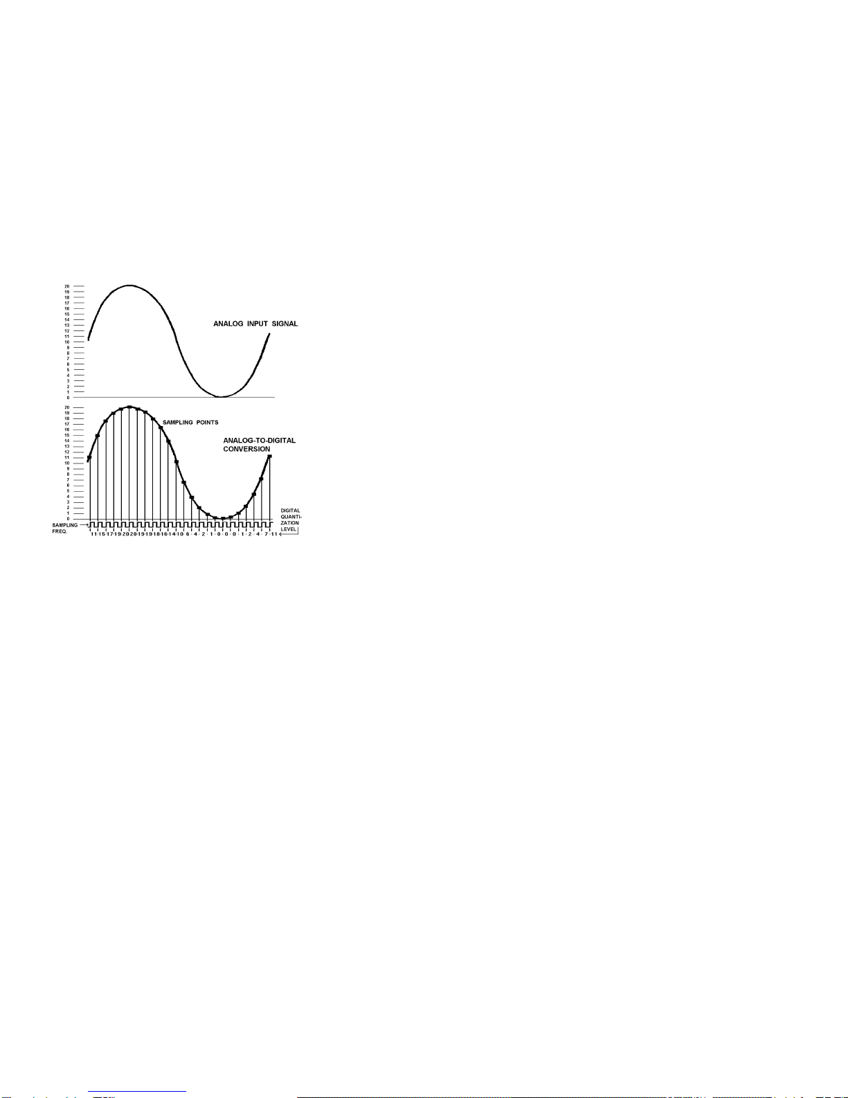
Converting an analog signal to digital is a two-
stage process, sampling and quantization. This
is illustrated in Figure 1. At regular inter-
vals, a sample-and-hold circuit instantaneously
freezes the audio waveform voltage and holds it
steady while the quantizing circuit selects the
binary code which most closely represents the
sampled voltage. Most digital audio is based on
a 16-bit PCM system. This means that the quan-
tizer has 65,536 (216) possible signal values to
choose from, each represented by a unique se-
quence of the ones and zeroes which make up the
individual code "bits" of the digital signal.
The number of these bits generated each second is a function of
sampling rate. At a relatively low sampling rate of 8 kHz (suitable
for voice) far fewer code bits are produced each second than, for
example, at the 44.1 kHz sampling rate used for commercial
compact disks. For a two-channel stereo signal at a 44.1 kHz
sampling rate, some 1.4 million bits are generated each second.
3
That's about five billion bits per hour, which is why you'll need at
least an 800 Megabyte hard disk to record an hour of compact
disk quality music.
To visualize the analog-to-digital conversion process, refer to Fig-
ure 1. At the top is one cycle of an analog input signal wave.
We've used a simple sine wave to make visualization easier. In
this example, the signal has a peak-to-peak amplitude of 20 units,
measured by the scale on the left. The sampling frequency is
many times higher than the signal being sampled and is shown
along the bottom of Figure 1. Once for each cycle of the sampling
frequency, the sample-and-hold circuit "slices" the input signal,
allowing the quantizing circuit to generate a (digital) number equal
to the closest (of the 65,536 possible discrete values) quantization
value of the input signal at the time the sample is taken. This re-
peats for each successive cycle of the sampling frequency and
Figure 1. Analog-to-Digital Conversion

4
the quantizer generates a continuous "bit stream" which repre-
sents the quantized signal. The continuous stream of digital audio
information is converted into a digitally modulated signal using a
technique known as linear pulse code modulation.
Digital-to-analog conversion (used in playback) is the exact oppo-
site of the analog-to digital conversion process and is illustrated in
Figure 2.
In digital-to-analog conversion, the PCM bitstream is converted at
the sampling frequency to a continuously changing series of
quantization levels which are individual "steps" of discrete voltage
equal to the quantization levels in the analog-to-digital process.
The shape of this continuously changing stream of quantization
levels approximates the shape of the original wave. This is shown
in the top half of Figure 2. This signal is then passed through a
low-pass filter, which removes the digital "switching noise." The
end result, shown in the bottom half of Figure 2 is an analog out-
put signal whose waveshape is a very close approximation of the
original analog input signal.
The foregoing is a very brief and, of necessity, oversimplified ex-
planation of how digital audio works. For the interested reader,
the book Principles of Digital Audio by Ken C. Pohlmann, copy-
right 1985 by Howard W. Sams, is highly recommended.

5
Figure 2. Digital-to-Analog Conversion

6
MINIMUM HARDWARE RECOMMENDED
!12MHz 386 PC or compatible
!28mSec average access hard disk
!1:1 Interleave hard disk controller
!Mouse
!VGA display
ADAPTER INSTALLATION
Make sure the main power to your computer is OFF. You will
need a full-size, 16 bit/AT slot. If you are unfamiliar with the inter-
nal design of your computer see its "Guide to Operations" manual
for step by step installation procedures.
Read JUMPER SETTINGS and CONNECTIONS for information
about configuring the adapter before plugging it into the slot.
JUMPER SETTINGS
The jumpers on the Z1, Z1e, SX-3, SX-33, SX-33b and SX-33e
have been preset at the factory to insure proper operation for
multimedia testing. Refer to Figures 11 & 12 in the back of the
manual for the jumper locations.
NOTE:These jumper numbers correspond to Z1/Z1e boards
marked 9000-2319-300x and SX-3/SX-33 9000-2334-300x
boards. Refer to Figure 13 for setting jumpers on earlier versions.
The interrupt is currently set to 10 by the JP7 jumper, but may be
changed to 2, 3, 5, 7, or 11 if the Windows drivers are configured
accordingly. Figure 3 illustrates the use of JP7.

7
2 3 5 7 10 11
""""""
""""""
""
Figure 3. Setting JP7 for audio IRQx 10
The I/O address is set to 380h, but may be changed to 180h,
220h, or 280h via jumpers JP5 and JP6. Figure 4 illustrates the
use of JP5 & 6.
NOTE:For the Z1, Z1e, SX-3, SX-33, SX-33e -The Z.WAV ad-
dress shown is always used, even if no Z.WAV is present.
"
"
JP5
"
"
JP6
AUDIO I/O
ADDRESS
Z.WAV
MPU-401 ADDRESS
X X 180h DISABLED
X - 220h 300h
- X 280h 320h
- - 380h 330h
NOTE: "X" indicates an enabled jumper
Figure 4. Setting JP5&6 to the audio I/O address &
Z.WAV address .
For Z1/Z1e only:
The joystick is enabled, but may be disabled by removing
the jumper from JP4.
The SCSI is enabled, but may be disabled by removing the
jumper from JP3. The address of the SCSI interface is
preset to CE00, but may be changed to CA00, C800, or
DE00 using JP1 and JP2.
Este manual sirve para los siguientes modelos
5
Tabla de contenidos
Otros manuales de Adaptador de Antex electronics


