
AmaizablazE 2100 Instrucciones de instalación

1
Installation & Operation Instructions
Models 2100 / 4100 / 7100
Read thoroughly before starting installation.
Save this manual for future reference.
SAFETY NOTICE
If this stove is not properly installed, a house fire may result. For
safety follow the installation directions.
Contact your local building or fire officials about restrictions and
installation requirements in your area.
Retain this information for future reference.
MODEL #________ SERIAL #_______ MFG. DATE __________
Working With Nature to Warm Your World
MANUFACTURED BY NESCO, INC. U.S.A.
Natural Energy Systems Company
Cookeville, TN

2
Table of Contents
General Safety Requirements ........................................................ 2
General Freestanding Installation/Direct Venting Instructions ..... 3
Mobile Home Installation .............................................................. 7
General Operation Instructions ...................................................... 8
Routine Maintenance Instructions ............................................... 12
Model 2100
Unit Preparation .................................................................. 13
Replacement Parts List ....................................................... 14
Unit Specifications ............................................................. 15
Unit Bimonthly Maintenance ............................................. 16
Electrical Wiring Diagram .................................................. 17
Model 4100
Unit Preparation .................................................................. 18
Unit Specifications ............................................................. 18
Fireplace Installation Instructions ...................................... 19
Replacement Parts List ....................................................... 21
Unit Bimonthly Maintenance ............................................. 22
Electrical Wiring Diagram .................................................. 23
Model 7100
Unit Preparation .................................................................. 24
Unit Specifications ............................................................. 25
Replacement Parts List ....................................................... 26
Unit Bimonthly Maintenance ............................................. 27
Electrical Wiring Diagram .................................................. 29
Problem Troubleshooting ............................................................ 30
Warranty Information .................................................................. 31
Warranty Registration Form ........................................................ 33

3
GENERAL SAFETY REQUIREMENTS
• SAFETY NOTICE: If this stove is not properly installed, a house
fire may result. For your safety, follow the installation directions.
Contact your local building or fire officials about restrictions and
installation requirements in your area.
• The manufacturer assumes no responsibility for equipment installed in
violation of either this manual or local codes and ordinances.
• During the first start up, curing of the heat exchanger and paint will take
place. You may have some smoke and odor for a short period. Open
windows for ventilation until process is complete.
• Use clean shelled corn for fuel only. Do not use seed corn. DO NOT
USE ANY OTHER TYPE FUELS!
• Never burn the unit without the burner box in place.
• WARNING: DO NOT CONNECT STOVE’S FLUE TO A CHIM-
NEY FLUE SERVICING ANOTHER APPLIANCE.
• Do not install a flue damper in the exhaust venting of this unit.
• Inspect and clean flues and chimney regularly. Inspections should be
conducted once a month during heating season.
• CAUTION: NEVER USE GASOLINE TYPE FUELS, LANTERN
FUELS, KEROSENE, DIESEL FUEL OR SIMILAR LIQUID
FUELS TO START A FIRE. KEEP ALL SUCH FLAMMABLE
LIQUIDS AWAY FROM THE UNIT WHILE IN USE.
• Use smoke detectors around the unit and locate a fire extinguisher rated
for class ‘A’ fires nearby.
• At the end of the heating season, remove all corn from hopper and auger
system.
• Do not extend Direct Vent Flue more than 15 feet without consulting the
manufacturer. Do not have more than two offsets in the flue. Intake air
could become restricted or overheated. Use U.L. listed type L pipe for
extending flue, DO NOT USE ALUMINUM LINERS.
• Always set POWER switch to “RUN/AUTO OFF” position and rotate
FUEL switch to “OFF” position (a click will be heard) for timed shut
down, or smoke may spill into home as the fire dies out. During a power
failure, smoke may spill into the home as the fire dies out.
• NESCO, Inc. is not liable for any smoke or soot damage.
• CAUTION: Due to the risk of electrical shock, unplug unit before
removing any access panel covers for servicing.

4
General Freestanding Installation/
Direct Horizontal Venting Instructions
NOTE: For direct horizontal venting, use only manufacturer’s
zero-clearance venting system.
SAFETY: Carefully read and follow all safety requirements previ-
ously set forth under the SAFETY REQUIREMENTS
before continuing with the following information.
CAUTION: When cutting through walls make sure you do not interfere
with wiring or pipes.
Do not extend Direct Vent Flue more than 15 feet without consulting the manufac-
turer. Do not have more than two offsets in the flue. Intake air could become
restricted or overheated. Use U.L. listed type L pipe for extending flue. Do not
use aluminum liners. Spacers may be required when extending direct vent flue if
using flexible liner. These can be purchased from your dealer or the stoves
manufacturer.
Contact your local building or fire officials about restrictions and installation
requirements in your area.
A. LOCATION PREPARATION
• For this type of installation, the stove must be located near an exterior wall and
should be located for the best heat circulation throughout the home. Also
consider wind conditions in your area. If possible, the exhaust vent should not
be placed on a wall that receives strong winds on a regular basis.
WARNING: See individual model sections for each model’s minimum clearance
to conbustibles. This is also noted on the Underwritiers Laboratory label affixed to
every stove.
• Review the location inside the home and check outside where the vent pipe will
be passing through the wall for any obstructions that may prevent proper
exhausting.
• Consider the design and construction of the building so as to minimize the need
to pass through existing structural supports such as wall studs, etc.
• Be sure that the exit termination of the direct vent (combined) intake air/exhaust
system is located in accordance with the following:
Not less than 3 ft. above any forced air inlet located within 10 ft. to either side.
Not less than 4 ft. below, 4 ft. horizontally to either side, or 1 ft. above
any door, window, or gravity air inlet into any building.
Not less than 2 ft. away from an adjacent building and not less than 7 ft.
above grade when located adjacent to public walkways.

5
B. MARKING & CUTTING HOLE IN EXTERIOR WALL
1. Attach adjustable glides to bottom corners of stove (not available on model
4100), and set at 1” in height, or if using any accessories such as a freestanding
base or leg set, these items should be installed on stove before proceeding on to
the next step. See the model details for instructions.
2. Temporarily position the stove on the floor protector in its final location. Be
sure to adhere to minimum clearance to combustibles. For minimum
clearance requirements, and floor protection requirements, for Model 2100 see
page 15, for Model 4100 see page 19, and for Model 7100 see page 25.
3. Level stove by adjusting the 4 adjustable glides.
4. Project both a horizontal and a vertical centerline of the stove’s combustion air
intake pipe. (See Figure 1.) For a corner application, determine by measuring
the horizontal centerline location of the elbow. (See Figure 2) On the same
centerline mark a center point on the wall. Using the point marked on the wall
as a center point, cut a 5 inch hole (or 6 inch, depending on model) through the
exterior wall. This can be accomplished with a variety of tools. Your needs
will vary depending upon what type of material you’ll be going through.
5. After cutting hole through wall, next move on to installing the vent kit from the
outside of the building.
CAUTION: WHEN CUTTING THROUGH WALLS MAKE SURE YOU DO
NOT INTEFERE WITH WIRING OR PIPES, ETC.
General Freestanding Installation/
Direct Horizontal Venting Instructions Continued

6
General Freestanding Installation/
Direct Horizontal Venting Instructions Continued
C. VENT KIT INSTALLATION PROCEDURES
Note the placement of the parts in order to facilitate reassembling.
1. From outside the building, caulk around the hole to ensure a durable seal to
prevent air and moisture from passing through.
2. Insert adjustable thimble with vent cap
mounting brackets located at top and
bottom. Mount thimble to the wall with
screws. The type of screws you use or
need for wall anchors will depend on the
material you are mounting to. (wood,
brick, etc.).
3. Remove vent cap.
CAUTION: Be careful while handling flex pip - Exposed end is very sharp.
Wearing heavy gloves is recommended while handling flex pipe.

7
4.
Now back inside, apply a small bead of
silicone around the outside of the stove’s
3 inch exhaust pipe; apply bead about 1/4
inch or less from end of pipe. (If this is a
corner installation, remove elbow
temporarily installed in Section B Step
4.) Slide the flex pipe connector over the
stove’s exhaust pipe. It will be a snug fit,
so twist and push the connector. It may
be helpful to start with the seam first.
General Freestanding Installation/
Direct Horizontal Venting Instructions Continued
NOTE: For corner installation, at this
time slide adjustable elbow pipe over
flex pipe and into stove’s intake pipe.
5. Move stove into final position while
guiding flex pipe into wall thimble. In
final position, stove’s intake pipe
should be slipped over wall thimble’s
intake pipe at least 1 1/2 inch.
6. From outside, use a hacksaw to cut flex
pipe 2 inches (minimum) from wall
surface. Be careful of all sharp edges.
Wearing heavy gloves is recom-
mended while handling flex pipe.
Do not cut the pipe too short, a little
extra is OK.
7. Loosen wing nut on vent cap and slip
adjustable collar completely over flex
pipe. Push vent cap over mounting
brackets on wall thimble. (Note: Be
sure screen is between mounting
bracket and vent cap on top.) While
holding in place insert top mounting
screw. Then tighten adjustable collar
to flex pipe. Wrap screen around
bottom of cap and install bottom
mounting screw and washer.
Important: Flex pipe must extend inside collar full depth to vent cap for proper
sealing, or exhaust can be pulled in with intake air.

8
Mobile Home Installation
When installing the unit in a mobile home or pre-manufactured home, in addition
to the installation instructions previously set forth, there are requirements man-
dated by the Housing and Urban Development (HUD) of the Federal Government,
which apply.
These requirements are as follows:
• The structural integrity of the home must be maintained. In other
words, you cannot cut a floor joist, wall stud or rafter truss when
installing your stove.
• Outside air must be vented to the combustion chamber. (As is when
using manufacturers direct vent kit.)
• The stove cannot be installed in any room used for sleeping.
• The stove must be anchored to the floor of the home. This may be
accomplished by using the following instructions.
Model 4100 - Freestanding Installation
A. Position angle brackets to pedestal (See
Illustration) and mark hole location. Then
drill a 9/32” hole through the base.
B. Secure brackets to base using 1/4 -20 x 3/4”
bolts, lock washers and nuts.
C. Position base exactly in its pre-determined
position and anchor to floor using 1/4”
diameter lag screws. (Length of screw will
vary depending on thickness of floor
protector.)
Model 4100 - Fireplace Installation
WARNING: To use Model 4100 as a fireplace
insert in a pre-manufactured home, the
existing fireplace must be U.L. listed for
use in premanufactured homes.
A. Anchor to hearth using 1/4” diameter lag
screws through the 2 holes in the bottom of
the stove. (One in each room air blower
compartment.)
D. Attach stove to base using hardware supplied with base kit, through the 3 holes in the
bottom of the stove. (One in each room air blower compartment and one in rear
compartment)
Model 2100 and 7100
A. The stove must be anchored to the floor of the home. This may be accomplished
by using the 11/32” holes located at the botom of the stove.
B. Anchor to the floor using minimum 1/4” diameter lag screws. Length of screw
will vary depending upon the thickness of floor protector, and whether or not you
are using the base kit option. (If using the leg set option, bolt leg directly through
floor protector to the floor using the hole in the foot of the leg.)

9
General Operating Instructions
A. CONTROL DESCRIPTIONS AND FUNCTIONS
POWER SWITCH
• START position - turns on the combustion air blower
and energizes the stove’s electrical system.
• OFF position - turns the power supply off immediately
to all components
• RUN/AUTO OFF position - applies main electrical
power to an AUTO OFF thermostat. This can be put
into effect once the room air blower motor/motors start.
This will allow the stove to shut down automatically
any time the fire dies out (i.c. the hopper runs out,
clinker not removed in a timely manner).
CAUTION: Improper shutdown can result in smoke
seeping in the hopper and home. Read and follow the
SHUT DOWN PROCEDURES carefully. (See page 10,
section D).
FUEL KNOB
• A rotary ON/OFF switch and fuel feed combination
• When set to “OFF” position (turned to maximum
counter-clockwise - a click will be heard), the switch
turns off power to the auger motor only. This prevents
fuel from feeding to the burner box.
• When turned clockwise from the OFF position, the
switch is turned on and supplies power to the auger
motor. The fuel feed rate increases as the switch is
turned clockwise, from a 1 through 10 setting.
NOTE: Stove is designed to burn clean - pieces of stalk or cob can block auger
and reduce feed rate of corn. Too much dust can cause blockage at feed tube
opening over burner box.
ROOM AIR KNOB
• This is a rotary switch which controls the speed of air flow that circulates
through the heat exhanger. The higher the fan speed, the more efficiently the
heat exchanger operates.
PRIME BUTTON
• A push button switch that is off when the button is not pressed. When pressed it
will manually operate the auger system.
• This control is used mostly when the hopper is completely empty. Fill the
hopper with corn, press and hold prime button until corn is delivered to burner
box. Auger is now primed for operation.
10
General Operating Instructions Continued
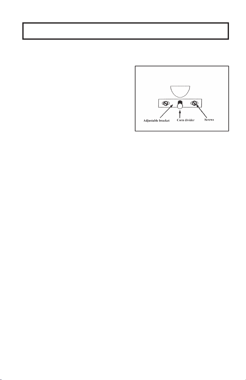
NOTE: Corn should distribute evenly to both sids of the burner box as it hits corn
divider. If adjustment is required, loosen screws slightly (requires 5/16” nut
driver, socket wrench, or equivalent tool) slide divider left or right towards side
feeding more heavily. Press and hold the PRIME button in order to check
adjustment, then retighten. If corn feeds to the front or rear of box too heavily,
bend divider up or down slightly.
IMPORTANT: Proper adjustment of the corn divider is necessary for the
efficient operation of your stove. If the corn is feeding too heavily towards the
back side of the burner box, as the clinker/ash builds up, excessive heat can
travel up the feed tube to the hopper, causing it to sweat. Also, it can eventually
block the corn dropping out of the feed tube opening, causing the corn to jam in
the feed tube and the fire to die out.
TIP: It is hard to see the effect of the adjustment without some clinker/ash
buildup. For accuate adjustment, re-check after stove has been burning for a
couple of hours. If readjustment is necessary, turn off power and fine tune by
bending the divider left,right, up or down. Once divider is properly set, no re-
adjustment should be required. The more accurately the corn feeds to the
center of the burner box, the better the quality of the fire, heat output, and
length of time between clinker removal will be.
4. Set POWER switch to “OFF” position and empty the burner box before
following LIGHTING PROCEDURE below.
C. LIGHTING PROCEDURE (For first time startup, see above.)
1. Fill hopper with clean shelled corn. Remove corn or ashes from burner box if
any are present. If hopper was empty, set POWER switch to “START”
position, then press and PRIME button until corn starts to feed into the burner
box. Set POWER switch back to “OFF position.
1. Fill hopper with clean shelled corn.
NOTE: Stove is designed to burn clean
corn only - pieces of stalk or cob can
block auger and reduce feed rate of corn.
2. Set POWER switch to “START”
position.
3. Prime feed system by pressing and
holding the PRIMER button until corn
feeds into the burner box. Release
button.
B. NEW INSTALLATION/FIRST TIME START UP
Este manual sirve para los siguientes modelos
2
Tabla de contenidos
Manuales populares de Cocina de otras marcas


Vermont Castings
Vermont Castings Intrepid 2 Manual de usuario

Italiana Camini
Italiana Camini CLASSICA Guía de inicio rápido

Avalon
Avalon Vashon Avanti DVS FS Manual de usuario

Spartherm
Spartherm ambiente a1 Manual de usuario

Dimplex
Dimplex MCFSTV12AU Manual de usuario

Warmlite
Warmlite WL46040 Manual de usuario