SPECIFICATIONS
DC
Ranses-.........-...-.....-..-.-.C€nter
scaleat 10 with
multiptiersXl,Xl0,
x 100,x 1000,
x 10K,
X 100K,X 1Mes.
PrintedCirGuill
Tube Complemenl:
Bortery:
Ranaes............-...... .... 1.5,
5, 15,50, 150,
500,
and 1500volts full scale.
Input Resistance ..........11Megohms (1 Megohm
in probe) on all ranges.
Circr1it....-...-..... ... Push -Pull batanced
bridge with 12AU7 t\rin
triode.
Accuracy ..... ... 13% full scale.
RMS Ran9es..................-1.5, 5, 15, 50, 150, 500,
1500 volts full scale.
Accuracy.............-.............15t;futl scale,
Peak-to-PeakRanges.....4,14,40,140,400,1400,
4000 volts.
4Y." 200aA mov€m€nt.
1% pr€cision
type.
Copperetchedotr lami
12AU7,
twin triode me-
6AL5, twin diode fuu
105-125volts,50-60cy-
clesAC.
1.5
volt "C" battery.
voltage, rcsistance,and AC voltage after rectification
by the fullwave rectifier. \
The meter employed
is an €xtremely stable,sensitive
200 microampere movement. The muttipliers are 1%
precision
type. Overall accuracjr
of tl1eDC functions is
13% of full scalereadins, and :!5% on AC functions.
A wide choice
of measurements
is provided arvDa you
seven ranses on DC, AC, and resistance. Bot}l RMS
and peak-to-peakAC voltages may b€ measurcd.
Your KNIGHT VTVM, through the useof the print-
cd circuit. saves
a greal d"at of t,dious wiring, as;ures
you ot a finisl'ed,nstrument
which compsres
closety
lo rhe original ensinFerina
modet,
ana irov:aes yoir
wrth an instl.ment \ orlh manv limes
irs low cost.
Before startina to build your KNIGHT VTVM,
check each palt against the Palts List on page 23. If
you are unableto identify someof the parts by sight,
locate them on the pictorial diagrams. Capacitor and
r€sistor values,if not printed on the part, canbe found
with the aid of the color codechat.
Hardware is listed in the last part of the parts List.
To keep our kits at the lowest possiblepdce, we frc,
quently weigh hardware raiher than to count it.
Therefore, do not be concerned if more nuts anar
machine screws, for example, are supplied than are
specified in the Parts List.
The only tools required for buildins your KNIGHT
VTVM are: Long-nosepliels, diasoral cutters, screw-
driver,
sei-scrF$d.ivcr. rnd a 50-wa||soldering
iron.
You may want to use a larger iron for soldedna the
contacts other than the pdnted circuit, but DO NOT
USE AN IRON LARGER THAN 50 WATTS FOR
MAKING THE SOLDER CONNECTIONS ON TIIE
PRINTED CIRCUIT. A good set of tools is listed at
t]le erd of tlje Parts List.
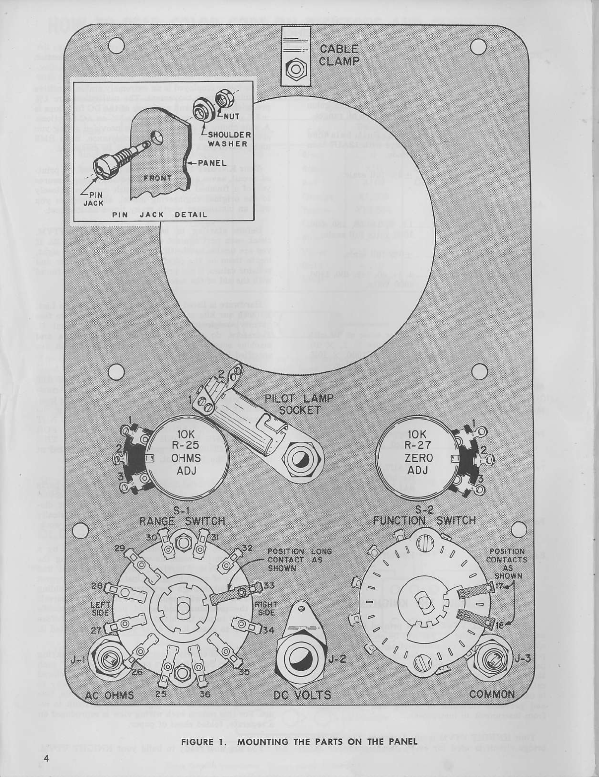
Study the pictorial diasrams and notehow the palts
are mounted.These
pictorial diagrams showthe actuat
location of all parts and wirirs. The schematic dia-
gram shows how the parts are cormect€d electrica.lly
aDd is helpful in understanding how Urc circuitg work.
The step-by-Etepinstructions wer€ prepaled by a
skilled techDicianwhite he was actually building the
KNIGHT VTVM. Therefore, they are the best and
fastest way of assembling this instrum€nt. We suggest
that you read throuah the instructions b€fore building
the VTVM. This will €nable you to Jamiliarize yourseu
with the proc€du.e and avoid possible erroru. We
invite you to use the blank parentheses,( ), beforc
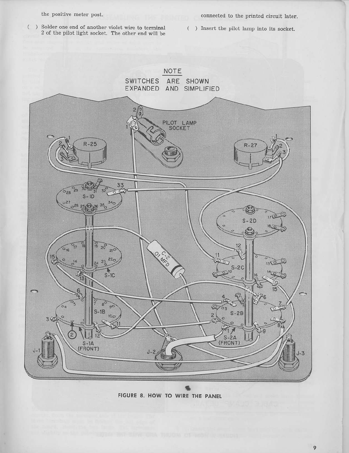
eachstep to check it off ajter you have completedit.
Each step is clearly illustraLedon an accompanying
line drawing. Somebuilders prefer to "cross out" each
wire and component on the drawings with a colored
pencil after it is instaUed.While an excellent way to
avoid mistakes, atrd hiAhly recommendedby us, this
procedure .esults in drawinAs that are difficult to re-
use.Fo! this reasor eachwiring view is reproducedon
a sepamte,folded sheetof paper.
You arenowreadyto build your KNIGHT VTVM.
AC
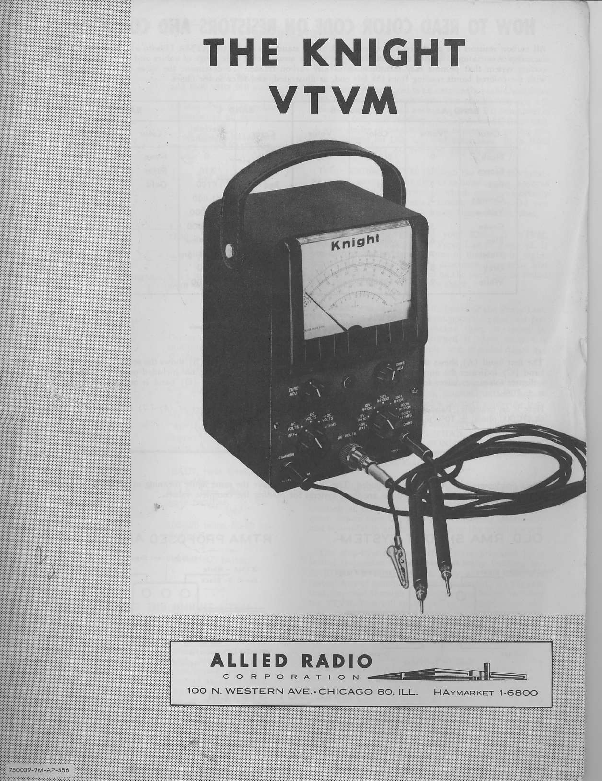
HOW TO BUITDTHE
KNIGHT
VTVM
Your KNIGHT VTVM usesa p nted circuit which
assuresyou that the VTVM will be an accurate, reti
abletest instrument regardlessof age.A sheetof cop-
per is bondedto a sheet of phenolic.When the wiring
pattern has been determined, the unused portion of
the coppe. sh€et is etched off leaviDgan exact dupli-
cation of the enginee ng prototype. Exact duplication
is one of the Areatest advantages of pdnted circuits,
and pr€vents variation in wiring aDd performance
from instrument to instrument.
Your KNIGHT VTVM is ait eiectronic. That is, the
bridge ci.cuit is used for every measurement of DC