AirCom AST24 Manual de usuario


AIRCOM®- 2022 - v. 1.0
AVAILABLE MODELS
mod. AST24
Double diaphragm pump with
flow rate of 24 l/min

EN
Index
WARNINGS!
Carefully read and follow all instructions and safety precautions
before using the product.
Instruction manual
MANUALS
Our manuals are available at aircom.it/en/support/manuals/
Or, by scanning the QR Code on this page.
Packing
Description
Technical features
Products and dimensions
Usage
Pipes connection
Start Work
Safety
Painting cycle
Pressure discharge
Maintenance
Cleaning
Filter replacement
Anomaly resolution
Scheduled maintenance
Spare parts and components
Disposal and Support
.04
.05
.06
.07
.08
.09
.10
.12
.13
.14
.15
.16
.17
.18
.19
.20
.26
PACKING
aircom.it .04
The pump is packed in a cardboard box. All components supplied as
standard are placed in the same package.
The weight of the equipment plus the packaging is ~22 Kg.
STORAGE
During transport and storage, make sure that temperatures between -15°C
and 40°C or 50°C for short periods not exceeding 24 hours are not
exceeded, which could damage the unit itself.
If the unit is to be stored, make sure it is stored in places with humidity
between 30% and 80%.
PLATE DATA
On the front plate, the equipment bears the manufacturer's identification
plate and the 2006/42/CE STANDARDS compliance plate, also represented
below.
The plate must not, under any circumstances, be removed, even if the
equipment is resold. For any communication with the manufacturer, always
quote the serial number (shown on the plate itself). On the body of the
pump there are some pictograms indicating safety warnings which must be
carefully observed by anyone preparing to use the painting unit. Failure to
comply with the provisions relieves the manufacturer from any damage or
injury to people or things that could derive from it and makes the operator
himself solely responsible towards the competent bodies. Replace the
nameplate and any removed, damaged or illegible stickers.
OBBLIGO DI
IMPIEGO DI
OCCHIALI E
MASCHERINA
EN

aircom.it .05
The equipment dealt with in this manual is a low pressure painting unit
which allows the use of any type of water-based or solvent-based paint.
Characterized by considerable practicality, versatility and ease of use, the
AST24 employs a pneumatically operated double diaphragm pump unit. The
spray system (usually a manual or automatic airbrush is used), allows the
delivery of special paints, textured, embossed, multicolored. It is possible to
paint small and medium-sized items, and to use them in applications where
a high level of surface finish is required.
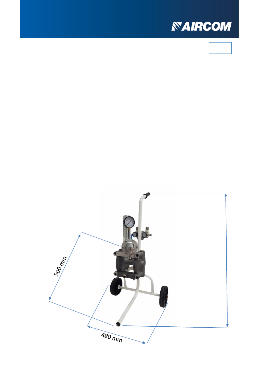
The modularity of the equipment allows you to purchase only the pump unit
and then customize it with a considerable number of accessories
(conventional or HVLP spray gun, pump trolley, gravity tank, wall fixing
system, suction systems, etc.) see drawing below:
Double air pressure
regulator group both at
the pump and at the
spray gun.
Rear main air inlet
cock with ¼” G fitting
Filter
Group to
regulate
pressure
Transport trolley
Pump
DESCRIPTION
EN

TECHNICAL FEATURES
aircom.it .06
The painting unit uses a pneumatic system that can be fed at a pressure
between 2 and 8 bar (from 28 to 114 psi). Compressed air is used to
obtain the movement of the two paint pumping membranes. All gaskets
are of a special type with high quality and high resistance; the valves are
in stainless steel, the seats are in stainless steel.
FEATURE AST24
CAPACITY
PRESSURE RATIO
OPERATING PRESSURE
NOMINAL PRESSURE
DROP TANK
PREVALENCE
AIR OUTLET FITTING
PAINT INLET FITTING
NOZZLE
WEIGHT
SOUND PRESSURE LEVEL
PEAK VALUE
24 Lt/min. (6 gal/min)
1:1
1÷ 8 bar (28÷114 psi)
6÷ 8 bar (85÷114 psi)
5 Lt. (1,25 gal)
15 metri
¼”M
F 1/2”
0,5 –5,0
15 Kg. (33 lb.)
Laeq=68,70 dB (A)
99,7 dB
EN
aircom.it .07
The AST24 series painting units are designed for painting ferrous material in
general, wood, plastics, fabrics, leathers. The products that can be supplied
are: paints, textured, embossed, multicolour paints, solvents, inks, oils,
resins. For the use of the equipment with particular products, the approval of
the manufacturer must be obtained, and the adaptation of the technical
characteristics of the unit for the processing of such products.
Solvents such as trichloromethane and chloromethylene (dichloromethane)
can chemically react with the aluminum which makes up most of the pump,
leading to dangerous explosions. We advise you to always read the technical
data sheet of the product you intend to apply very carefully, avoiding the use
of materials that contain this type of solvent. Do not use regenerated
solvents (cleaning thinners), make sure they are free from acids (caused by
regeneration); these acids are responsible for the corrosion of the gun.
PRODUCTS AND DIMENSIONS
960
mm
EN

aircom.it
Before using the paint pump, check that it has not suffered damage due
to transport or storage conditions.
Also check that all the optionals ordered and all the components supplied
as standard are contained in the packaging.
Always wear the prescribed PPE; gloves, mask, goggles, in compliance
with workplace safety regulations. As a first step, it is necessary to make
sure that the lines are able to correctly feed the pump, in compliance
with the safety standards.
The unit is supplied with a double pressure regulator, it is recommended
to supply with a pressure of 6÷8 bar Max.
It is recommended to use dry compressed air for best painting results.
The drawing indicates the connection points of the equipment to the
pneumatic network.
.08
USAGE
Manometer
Sprayer manometer
Pressure and air
pump regulator
Sprayer air
pressure regulator
Rear air inlet fitting
Adapter plate
EN

aircom.it .09
2
7
5 3
6
8
4
PIPES CONNECTION
1
The pump must be placed in an easily
accessible position but in such a way
that it does not hinder the operator and
that it is not exposed to jets of paint.
•Connect the twin hose to both the
pump and the gun. The twin tube is
of two colors; (WHITE) for product,
and (BLUE) for atomizing air.
Important: pay close attention to the
connection, as the fittings of the blue hose
are identical to the fittings of the white
hose.
Do not reverse the pipes. Connect the
product passage pipe (WHITE) to the
product delivery pipe connection (Pos. 1).
Connect the atomizing air hose (BLUE) to
the atomizing air connection (Pos. 3).
• Connect the air supply pipe (minimum
internal diameter of the pipe 8 mm) to
the pump air connection fitting (Pos. 4).
• Connect the suction pipe (tightening
tightly) to the paint suction pipe fitting
(Pos. 2). If you have a gravity tank,
screw the tank to the paint suction pipe
connection using the 90° extension
supplied with the tank.
• Connect the return pipe (tightening
tightly) to the connection of the return
cock (Pos. 5). If you have a gravity
tank, recirculation takes place through a
rilsan tube (to be screwed to the return
tap fitting) and a curved end to be
inserted into the hole in the tank lid
EN

aircom.it .10
START WORK
SUCTION SYSTEM
• All our pumps are tested with chemical water, therefore a light film of
oil is deposited in the product passages. When starting for the first
time, it is recommended to circulate the solvent in the pump before
starting work.
• Immerse the vacuum system in a container of solvent.
• Make sure that the return cock (Pos. 5) is open.
• Open the line cock. Turn the engine air regulator knob to the right
(Pos. 6). Adjust the pressure to two bars (28 psi).
The pump begins to draw solvent from the container through the dip
tube and puts it back into the container through the return tube,
washing the pump body.
• During the washing phase of the pump body, the supply air to the
gun must be closed. Turn the atomizing air pressure regulator
handwheel to the left (until the end of the stroke). Let the solvent
circulate for a few seconds.
• Close the return cock; the solvent is sent to the gun through the
delivery tube. Adjust the thrust pressure of the product to 1 bar by
turning the handwheel of the paint pressure regulator to the right (Pos.
7).
• Rest the spray gun on a container, pull the spray gun control lever,
letting the solvent flow out for a few moments, then release the control
lever.
• Open the return cock and lift the suction system from the solvent
container, the pump empties through the recirculation pipe. Shut off
the pump supply air as soon as the system has completely emptied.
EN
Tabla de contenidos
Otros manuales de Bomba de agua de AirCom


Manuales populares de Bomba de agua de otras marcas


Sykes AmeriPumps
Sykes AmeriPumps GP100M Guía de solución de problemas

DUROMAX
DUROMAX XP WX Series Manual de usuario

BRINKMANN PUMPS
BRINKMANN PUMPS SBF550 Manual de usuario

Franklin Electric
Franklin Electric IPS Manual de usuario

Xylem
Xylem e-1532 Series Manual de usuario

Milton Roy
Milton Roy PRIMEROYAL Manual de usuario