Agrimate AMP-768-PRO 4S Series Manual de usuario

User Manual
BEFORE OPERATING THIS MACHINE,
PLEASE READ THESE INSTRUCTIONS CAREFULLY
Portable Power Sprayer
AMP-768-PRO 4S
AMP-968-PRO 4S
DISCLAIMER: DUE TO CONSTANT UPGRADATION, FEATURES AND SPECIFICATIONS ARE
SUBJECT TO CHANGE WITHOUT NOTICE
Portable Power Sprayer
Portable Power
Sprayer
Portable Power Sprayer
Portable Power
Sprayer
2
CAUTION
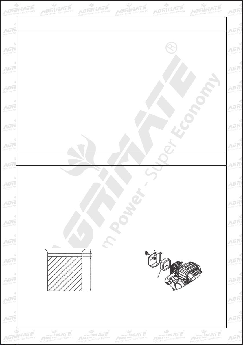
Refuel
Use the mixture of the gasoline and the two stroke engine oil, the volume ratio is 25-30:1 (Fig-1)
Check and clean the air filter
The air filter must be often cleaned, or the polluted air filter will lower the output power of the
engine. If the core is blocked by dust, use gasoline to clean the core and the inside of the air filter,
then dip in the oil, wring oil out and put the core back (Fig 2)
PREPARATION
1. Stop running the gasoline engine before the tank is refueled, and ensure that the gasoline
engine is far from the fire. Against the position, discharge the exhaust gas from the rooms,
channels using gasoline engine or any other closed places.
2. Forbid to touch the muffler and the body when the gasoline engine runs and just stops.
3. Don’t touch the ignition plug cap and wires, to avoid the electrical shock
4. Forbid children and persons unconcerned to touch the gasoline engine.
5. Ensure the cooling of the muffler and the body, cover the gasoline engine after daily work.
6. Against the problem, the damage or the misfire of gasoline engine, check and maintain the
gasoline regularly and clean the deposit carbon in the muffler and in the cylinder exhaust.
7. Forbid to use pure gasoline (without two-stroke engine oil) as fuel.
8. Against the damage of gasoline engine and the instruments, forbid to accelerate abruptly, to
run speedily and stop abruptly.
9. Forbid the drunk, the dizzy and the pregnant to use the gasoline engine.
1. The FC Two-stroke engine oil
25. The Gasoline The Core
Fig 1 Fig 2
3
START UP
1. After the engine starts, run 3-5 minutes at a low speed
2. When the engine is heated enough, adjust the throttle handle to the corresponding speed.
3. Note: don’t accelerate abruptly due to bad lubrication of the engine at the beginning of startup.
4. Avoid the speedy idle motion and over speed motion. If the throttle is totally opened, the
engine will run over speed, which not only shortens the service life of the engine but also
causes more problems in the engine.
1. Reduce the gasoline engine to the slowest speed and run 3-5 mins
2. Press the stop switch to stop the engine.
RUNNING
STOPPING
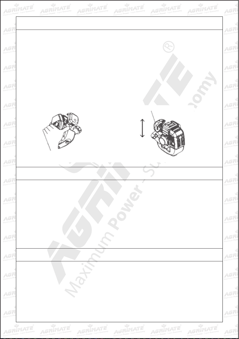
1. Turn on the gasoline switch until the gasoline flows out the clear plastic pipe. (Fig 3)
2. Close the choke totally (Fig 4)
If the engine is heated, the choke must be totally opened.
3. Open half the throttle.
4. Draw the starter several times slowly, and then draw quickly.
Note: If the excessive gasoline causes the difficult start, take down the ignition plug and the
input pipe, open the choke and the throttle totally, draw the starter several times then install
the input pipe and start the engine. After the startup, open the choke totally.
Fig 3
Fig 4
Open
Close
The Choke Handle

4
MAINTENANCE
1. Daily check
•Checkallscrewsandnuts
•Checkoilleakageorairleakage
2. Check after running 20 hours
•Cleanthecoreoftheaircleaner
•Cleanthegasolinelter
3. Check after running 50 hours
•Refastenthenutsofthecylinder
•Clean the accumulated carbon both in the combustion chamber and in the exhaust
of the cylinder
•Cleantheaccumulatedcarbonintheignitionplug,adjusttheclearanceto0.6mm(Fig5)
•Cleantheaccumulatedcarbonbothintheintakeandintheexhaustofthemufer(Fig6,7)
Fig 5 Fig 6 Fig 7
If the gasoline engine isn’t used for a long time, it must be maintained as follows:
1. Remove the fuel in the tank and in the carburetor, close the choke totally, draw the starter
3-5 times.
2. Take down the spark plug, add certain engine oil from the spark plug hole into the cylinder, and
draw the starter 2-3 times to move the piston to the top dead center, then install the spark plug.
3. Use the soft cloth with engine oil to clean the surface of the engine, stor the engine in a dry
and windy place for the next use.
STORAGE

5
TROUBLE SHOOTING
1. Fail to start
•Oilswitchisnotturnedon
•Gasolineismixedwithwater,replaceit
•Theignitionplughasaccumulatedcarbonorhasbeenbroken
•Poorcontactofthehighvoltagewirewiththesparkplug
2. The engine can start, but can’t run fast
•Thechokeiseitheropenorclosedfully
•Theratioofengineoilandthegasolineisnormalornot
•Maybethereiswateringasoline
3. The gasoline engine can run, but has not enough power
•Maybethecoreoftheairlterisblockedbydust
•Maybethecylinderexhaustandthemuferareblockedbyaccumulatedcarbon
•Thepiston,thepistonringsandcylinderhavebeenbadlywornout
•Maybethegasolinelterisblockedbydust
•Thebodyorthetopoftheshafthasoilleakageandairleakage
4. The gasoline engine stops suddenly when running
•Runoutofthegasoline
•Thehighvoltagewiredrops
•Theignitionplughasaccumulatedcarbonorhasbeenbroken
•Thegasolinelterisblockedbydust
•Maybethereiswaterinthegasoline
•Theairholeofthetanklidisblockedbydust
6
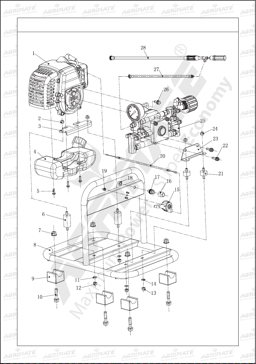
STAND DIAGRAM OF AMP-768 PRO | AMP-968 PRO
7
S.N Part No. Description
1 AMP 768 PRO S01 Engine
2 AMP 768 PRO S02 Nut M6
3 AMP 768 PRO S03 Engine stand
4 AMP 768 PRO S04 Oil tank
5 AMP 768 PRO S05 Screw M5Xl6
6 AMP 768 PRO S06 Joint
7 AMP 768 PRO S07 Nut M8
8 AMP 768 PRO S08 Frame
9 AMP 768 PRO S09 Joint
10 AMP 768 PRO S10 Bolt M8*35
11 AMP 768 PRO S11 Washer M6
12 AMP 768 PRO S12 Nut M6
13 AMP 768 PRO S13 Nut M6
14 AMP 768 PRO S14 Washer M6
15 AMP 768 PRO S15 Flex acceler ator
16 AMP 768 PRO S16 Engine stop protector
17 AMP 768 PRO S17 Engine stop switch
18 AMP 768 PRO S18 Nut M8
19 AMP 768 PRO S19 Nut M5
20 AMP 768 PRO S20 Cable
21 AMP 768 PRO S21 Joint (pump)
22 AMP 768 PRO S22 Bolt M6*16
23 AMP 768 PRO S23 Pump stand
24 AMP 768 PRO S24 Nut M6
25 AMP 768 PRO S25 Pump
26 AMP 768 PRO S26 Bolt M6*16
27 AMP 768 PRO S27 Outlet hose
28 AMP 768 PRO S28 spray gun
STAND PARTS LIST OF AMP-768 PRO | AMP-968 PRO

8
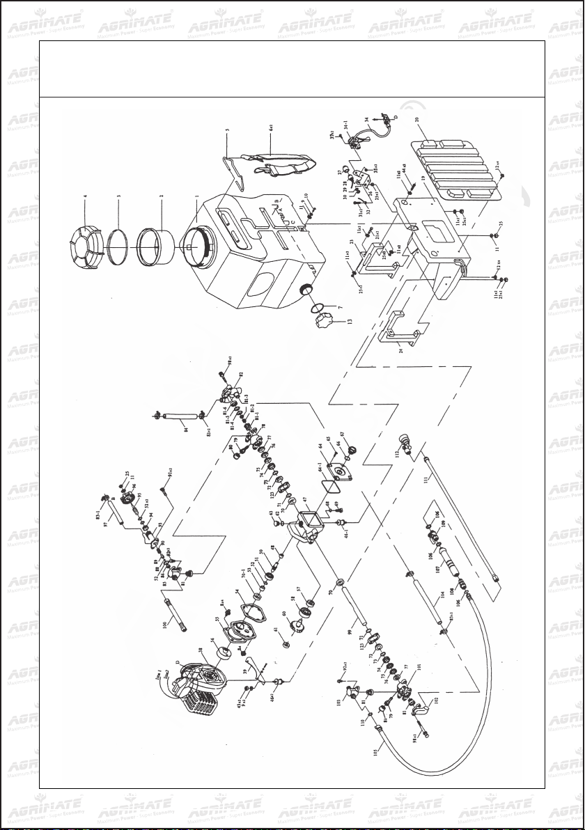
ENGINE SPARE PARTS DIAGRAM OF AM-P768-PRO
9
ENGINE SPARE PARTS LIST OF AM-P768-PRO
S.N. Part No. Description
1 AMP 768 PRO E01 SCREW
2 AMP 768 PRO E02 CLEANER OUTSIDE COVER
3 AMP 768 PRO E03 CLEANER ELEMENT
4 AMP 768 PRO E04 SCREW M5X55
5 AMP 768 PRO E05 CLEANER INSIDE COVER
6 AMP 768 PRO E06 SCREW ST4.2X12-F-H
7 AMP 768 PRO E07 CHOKE
8 AMP 768 PRO E08 CHOKE HANDLE
9 AMP 768 PRO E09 CARBURATOR
10 AMP 768 PRO E10 GASKET
11 AMP 768 PRO E11 SCREW M5X20
12 AMP 768 PRO E12 INLET MANIFOLD
13 AMP 768 PRO E13 CYINDER WASHER
14 AMP 768 PRO E14 ANNUL B3X10
15 AMP 768 PRO E15 SCREW M4X16
16 AMP 768 PRO E16 FAN COVER
17 AMP 768 PRO E17 CLUTCH STEP SCREW
18 AMP 768 PRO E18 WASHER
19 AMP 768 PRO E19 CLUTCH SHOE COMP.
20 AMP 768 PRO E20 WASHER
21 AMP 768 PRO E21 CLUTCH SPRING
22 AMP 768 PRO E22 NUT M8X1
23 AMP 768 PRO E23 WASHER 8
24 AMP 768 PRO E24 STOP CORD COMP
25 AMP 768 PRO E25 CLIP
26 AMP 768 PRO E26 PRIMARY CORD GROMMET
27 AMP 768 PRO E27 MAGNETO STATOR
28 AMP 768 PRO E28 MAGNETO ROTOR
29 AMP 768 PRO E29 SCREW M5X25
30 AMP 768 PRO E30 FRONT HALF CRANK CASE
31 AMP 768 PRO E31 GUIDE PLATE
32 AMP 768 PRO E32 CRANK CASE GASKET
33 AMP 768 PRO E33 OIL SEAL
34 AMP 768 PRO E34 BALL BEARING 6001/P5
35 AMP 768 PRO E35 KEY
36 AMP 768 PRO E36 CRANK SHAFT COMP.
37 AMP 768 PRO E37 REAR HALF CRANK CASE
38 AMP 768 PRO E38 STARTER PULEEY ASS’Y
39 AMP 768 PRO E39 STARTER PAWL SPRING
40 AMP 768 PRO E40 STARTER PAWL
41 AMP 768 PRO E41 SCREW M5X10
42 AMP 768 PRO E42 RECOIL SPRING
S.N. Part No. Description
43 AMP 768 PRO E43 STARTER ROPE REEL
44 AMP 768 PRO E44 RECOIL STARTER BODY
45 AMP 768 PRO E45 ROPE GUIDE
46 AMP 768 PRO E46 ROPE
47 AMP 768 PRO E47 STARTER HANDLE
48 AMP 768 PRO E48 GASKET
49 AMP 768 PRO E49 SCREW M5X14
50 AMP 768 PRO E50 COVER
51 AMP 768 PRO E51 COVER
52 AMP 768 PRO E52 SCREW M4X12
53 AMP 768 PRO E53 PLUG CAP
54 AMP 768 PRO E54 CLICK SPRING
55 AMP 768 PRO E55 PLUG COVER
56 AMP 768 PRO E56 SPARK PLUG
57 AMP 768 PRO E57 SCREW M5X20
58 AMP 768 PRO E58 GASKET
59 AMP 768 PRO E59 MUFFLER COMP.
60 AMP 768 PRO E60 SCREW M5X50-10.9
61 AMP 768 PRO E61 CYLINDER
62 AMP 768 PRO E62 CYLINDER WASHER
63 AMP 768 PRO E63 PISTON RING
64 AMP 768 PRO E64 PISTON
65 AMP 768 PRO E65 PISTON PIN
66 AMP 768 PRO E66 NEEDLE BEARING
67 AMP 768 PRO E67 PISTON PIN CIRCLET
68 AMP 768 PRO E68 FUEL TANK LID
69 AMP 768 PRO E69 GASKET
70 AMP 768 PRO E70 AIRINLET MOUTH
71 AMP 768 PRO E71 INSIDE COVER
72 AMP 768 PRO E72 CASING
73 AMP 768 PRO E73 CHAIN
74 AMP 768 PRO E74 FUEL PIPE
75 AMP 768 PRO E75 FUEL PIPE
76 AMP 768 PRO E76 PLUG
77 AMP 768 PRO E77 CLEANER
78 AMP 768 PRO E78 FUEL TANK LID
79 AMP 768 PRO E79 SCREW M5X16
80 AMP 768 PRO E80 STARTER PULLEY ASSY
81 AMP 768 PRO E81 STARTER
10
TANK & PUMP SPARE PARTS DIAGRAM OF SPRAYER
AMP-768-PRO | AMP-968-PRO
Este manual sirve para los siguientes modelos
1
Tabla de contenidos
Otros manuales de Pistola pulverizadora de pintura de Agrimate

Agrimate
Agrimate AM-708-PRO-2S-WC Manual de usuario

Agrimate
Agrimate AM-708 Manual de usuario

Agrimate
Agrimate AM 22 AUTO Manual de usuario

Agrimate
Agrimate AM ZOOM Manual de usuario

Agrimate
Agrimate AMP-769-HCP Manual de usuario

Agrimate
Agrimate AM-K26708 Manual

Agrimate
Agrimate AM-708T Manual de usuario

Agrimate
Agrimate AM22-NT Manual de usuario

Agrimate
Agrimate AM-405E-ELITE Manual de usuario

Agrimate
Agrimate AM-666-NEO 2S Series Manual de usuario


