AES XXS-3 Manual de usuario

- 1 -
Installation & Operation Manual
PROTEAM XXS Swimming Pool Heat Pump
Model: XXS-3
XXS-4
XXS-6

- 2 -
Please keep installation manual in a safe place and read it carefully before using.
- The unit must be installed by professional technicians according to this manual.
-If the unit is installed in an area that is prone to lightning strikes, please ensure to take appropriate lightning
protection measures.
- The manufacturer shall not be responsible for any damage caused to people, objects or equipment due to failure
to follow the instructions and comply with the procedures contained in this manual. Any use of this product for
functions other than described in the manual shall be considered as dangerous.
- Make sure the heat pump is installed in a well-ventilated place, away from anything which could cause fire.
- Do not weld any pipes if there is refrigerant inside machine. If you need to fill gas into the unit, make sure it is
in an open, well-ventilated area and not in a confined space.
- Always drain all water inside the heat pump during winter or when the ambient temperature drops below
0℃: failure to do so may result in damage to the titanium heat exchanger due to freezing, and it will not be
covered by warranty.
- Always disconnect the power supply if you want to open the cabinet to look inside the heat pump as there
is high voltage electricity inside.
- Make sure the display controller is in a dry area to prevent damage caused by humidity.
- Filling of gas must be carried out by professionals with R32 operating license.

- 3 -
* INDEX
1. Specifications
2. Dimensions
3. Installation and connection
4. Electrical wiring
5. Display controller operation
6. Troubleshooting
7. Exploded diagram
8. Maintenance

- 4 -
1. Specifications
1.1 Technical data pool heat pumps
Model
XXS-3
XXS-4
XXS-6
Advised pool volume(m3)
≤20
≤28
≤37
Power Supply
220V~240V/1/50Hz
Heating Capacity at Air 26℃,Water 26℃Hygro 80%
Heating Capacity (Kw)
3.05
4.00
5.60
Power Input (kW)
0.56
0.73
1.03
COP
5.45
5.45
5.43
Heating Capacity at Air 15℃,Water 26℃Hygro 70%
Heating Capacity (kW)
2.51
3.10
4.95
Power Input (kW)
0.55
0.69
1.09
COP
4.53
4.52
4.54
Max Power Input (kW)
0.95
1.28
1.55
Max Current (A)
4.4
5.8
7.0
Refrigerant
R32
R32
R32
Heat Exchanger
Titanium
Titanium
Titanium
Air Flow Direction
Horizontal
Horizontal
Horizontal
Water Flow Volume(m3/h)
1.5
2.0
3.0
Net Dimensions (L*W*H)(mm)
380*280*350
380*280*350
420*360*436
Package Dimensions (L*W*H)(mm)
440*355*405
440*355*405
480*435*495
Working temperature range (℃)
8~43
8~43
8~43
Noise (dB)
28
29
29
Net Weight (kg)
18
20
24
Gross Weight (kg)
20
22
26
*Above data is subject to modification without prior notice.

- 5 -
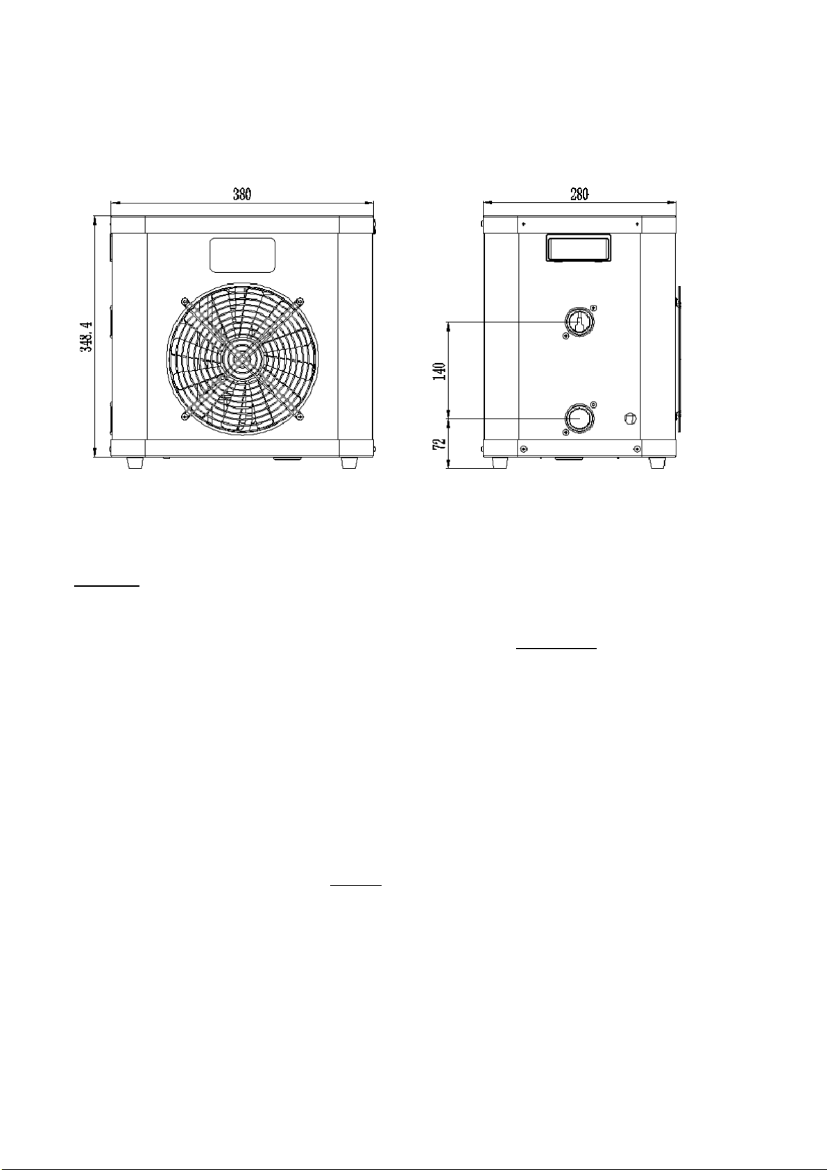
2. Dimensions
3.Installation and connection
Attention:
Please observe the following rules when installing the heat pump:
1. Any addition of chemicals must take place in the piping located downstream (after) from the heat pump.
2. Always keep the heat pump in an upright position. If the unit has been held at an angle, wait at least
24 hours beforestarting the heat pump.
3.1 Heat pump location
The unit will work properly in any desired location as long as the following three requirements are met:
1. Fresh air –2. Electricity –3. Swimming pool filters
The unit may be installed in virtually any outdoor location as long as the specified minimum distances to other
objects are maintained. Please consult your installer for installation on an indoor pool.
ATTENTION: Never install the unit in a closed room with limited space (air volume) in which the air expelled
from the unit will be reused, or close to shrubbery that could block the air inlet. Such locations impair the
continuous supply of fresh air, resulting in reduced efficiency and possibly preventing sufficient heat output.

- 6 -
3.2 Initial operation
Note: In order to heat the water in the pool (or hot tub), the filter pump must be running so that water
is circulated through the heat pump. The heat pump will not start up if the water is not circulating.
3.3 Electrical connection
Before connecting the unit, verify that the supply voltage matches the operating voltage of the heat pump.
An RCD plug has been included with the power cable to provide electrical protection.
Attention:
Ensure the power plug is secure
If the plug is not secure, it may cause
an electric shock, over-heating or
fire.
Never pull out the power plug during
operation
This may cause an electric shock or
a fire due to over-heating.
Never use damaged electric wires
or unspecified electric wires.
This may cause an electricshock or
a fire.

- 7 -
After all connections have been made and checked, carry out the following procedure:
1. Switch on the filter pump. Check for leaks and verify that water is flowing from and to the swimming pool.
2. Connect power to the heat pump and press the On/Off button on the control panel. The unit will
start up after the time delay expires (see below).
3. After a few minutes, check whether the air blowing out of the unit is cooler.
4. When you turn off the filter pump, the unit should also switch off automatically.
Depending on the initial temperature of the water in the swimming pool and the air temperature, it may take
some time to heat the water to the desired temperature. A good swimming pool cover can dramatically reduce
the required length of time to heat the pool and the energy required to maintain the desired temperature.
Time delay - The heat pump has a built-in 3-minute start-up delay to protect the circuitry and avoid excessive
contact wear. The unit will restart automatically after this time delay expires.
The first time the unit power is switched on or after any power interruptions, the heat pump starts 10s after
pressing ‘ON/OFF’ button.
3.4 Condensation
The air drawn into the heat pump is quickly cooled by the operation of the heat pump to heat the pool water,
which may cause condensation on the fins of the evaporator. The amount of condensation may be as much as
several litres per hour at high relative humidity. This is sometimes mistakenly regarded as a water leak.

- 8 -
4.Electrical wiring
4.1 Swimming pool heat pump wiring diagram
3kW
NOTE:
(1) The above electrical wiring diagram is only for your reference, please check the wiring diagram on the unit.
(2) The swimming pool heat pump must be properly grounded/earthed. Even though the heat exchanger is
electrically isolated from the rest of the unit, grounding the unit is still required to protect against short circuits
inside the unit.
Disconnect: A disconnection device (circuit breaker, fused or un-fused switch) should be located within sight of
and readily accessible from the unit. This is common practice on commercial and residential heat pumps. It
prevents remotely energizing unattended equipment and permits turning off power at the unit while the unit
is being serviced.

- 9 -
5. Display controller operation
5.1 LED wire controller Interface
*When the heat pump is running or on standby, the display shows the water inlet temperature.
*When the heat pump is powered on, the display shows ‘OFF’
*Red LED will go on when you turn on the machine.
5.2 Turn on/off the heat pump
Press to turn on the heat pump, the LED display shows the water setting temperature for 5s, and
then shows the water inlet temperature.
Press again to turn off the heat pump.
5.3 Set the desired water temperature
Press or directly to adjust the desired water temperature (parameter d, range:.15—40℃), the
setting will be saved after 3 seconds.
You can also adjust Parameter d to set the desired water temperature.
NOTE: There is a 3 min time delay at start-up to protect the compressor.
NOTE: the heat pump can run only if the water circulation/filtration system is running.

-10
-
5.4 Parameter checking & adjustment
Hold button for 5 seconds to enter parameter checking mode, Press or to check the
Parameters shown below.
Press again to enter the current parameter adjustment screen, press or to make the
adjustment, then press to save the setting.
Parameter
Description
Range
Default
Remark
A
Inlet water temp.
-19~99℃
Real data
C
Ambient temp.
-19~99℃
Real data
d
Desired water temp.
15℃~40℃
27℃
Adjustable
H
Return ambient temp. difference
1℃~10℃
2℃
Adjustable
J
Power-failure protection
0~1
1 (Yes)
Adjustable
O
Lowest ambient temp. for operation
0℃~15℃
10℃
Adjustable
5.5 Restore factory settings
Hold
and
for 10 seconds to restore the factory settings.
NOTE: The other parameters which are not shown below are reserved for other functions and are not
applicable to this unit.
Este manual sirve para los siguientes modelos
2
Tabla de contenidos
Otros manuales de Bomba de agua de AES
Manuales populares de Bomba de agua de otras marcas

Sykes AmeriPumps
Sykes AmeriPumps GP100M Guía de solución de problemas

DUROMAX
DUROMAX XP WX Series Manual de usuario

BRINKMANN PUMPS
BRINKMANN PUMPS SBF550 Manual de usuario

Franklin Electric
Franklin Electric IPS Manual de usuario

Xylem
Xylem e-1532 Series Manual de usuario

Milton Roy
Milton Roy PRIMEROYAL Manual de usuario