AeroComm CN4490 Manual de usuario

VERSION 1.0

Technical Support: Phone: 800.492.2320
E-mail: support@aerocomm.com
Web: www.aerocomm.com/support
Sales: Phone: 800.492.2320
E-mail: sales@aerocomm.com
Web: www.aerocomm.com

Document Information
Copyright © 2008 AeroComm, Inc. All rights reserved.
The information contained in this manual and the accompanying software programs are copyrighted and all rights are
reserved by AeroComm, Inc. AeroComm, Inc. reserves the right to make periodic modifications of this product without
obligation to notify any person or entity of such revision. Copying, duplicating, selling, or otherwise distributing any
part of this product or accompanying documentation/software without the prior consent of an authorized
representative of AeroComm, Inc. is strictly prohibited.
All brands and product names in this publication are registered trademarks or trademarks of their respective holders.
This material is preliminary
Information furnished by AeroComm in this specification is believed to be accurate. Devices sold by AeroComm are
covered by the warranty and patent indemnification provisions appearing in its Terms of Sale only. AeroComm makes
no warranty, express, statutory, and implied or by description, regarding the information set forth herein. AeroComm
reserves the right to change specifications at any time and without notice.
AeroComm’s products are intended for use in normal commercial and industrial applications. Applications requiring
unusual environmental requirements such as military, medical life-support or life-sustaining equipment are specifically
not recommended without additional testing for such application.
Limited Warranty, Disclaimer, Limitation of Liability
For a period of one (1) year from the date of purchase by the OEM customer, AeroComm warrants the OEM
transceiver against defects in materials and workmanship. AeroComm will not honor this warranty (and this warranty
will be automatically void) if there has been any (1) tampering, signs of tampering; 2) repair or attempt to repair by
anyone other than an AeroComm authorized technician.
This warranty does not cover and AeroComm will not be liable for, any damage or failure caused by misuse, abuse,
acts of God, accidents, electrical irregularity, or other causes beyond AeroComm’s control, or claim by other than the
original purchaser.
In no event shall AeroComm be responsible or liable for any damages arising: From the use of product; From the loss
of use, revenue or profit of the product; or As a result of any event, circumstance, action, or abuse beyond the control
of AeroComm, whether such damages be direct, indirect, consequential, special or otherwise and whether such
damages are incurred by the person to whom this warranty extends or third party.
If, after inspection, AeroComm determines that there is a defect, AeroComm will repair or replace the OEM transceiver
at their discretion. If the product is replaced, it may be a new or refurbished product.

DOCUMENT INFORMATION
1-800-492-2320
www.aerocomm.com
Revision Description
Version 1.0 12/27/07 - Initial release version.

Contents
CONNEXNET RF TRANSCEIVER 1
ConnexNet Features 1
Overview 1
SPECIFICATIONS 2
HARDWARE INTERFACE 3
LAN Port (RJ-45 connector) 4
Power-over-Ethernet 4
Auto MDI/MDIX Interface 4
CONFIGURATION UTILITY 5
Overview 5
Software Installation 5
PC Settings Page 6
Port1/Port2 Options 7
Other Options 7
Status Bar 8
About Button 8
Configure Page 9
Read Radio Button 9
Write Radio Button 10
Show Defaults Button 10
Pairing Button 10
Load / Save to File Buttons 10
Port 1/Port 2 Buttons 11
Hex/Decimal Button 11
Terminal/Chat Page 12
Send Button 12
Hexadecimal / ASCII Display 12
Range Test Page 13
Test Selection 13
Transmit Packet Selection 14
Test Type 14
Receive Packet Display 14
DEVICE SETUP 15
TCP Socket 15
Connecting via TCP socket 15
Changing IP settings 15
Virtual COM Port 16
Virtual COM Port installation 16
Connecting directly to a LAN port 20
Assigning ConnexNet a Static IP 20
Assigning your PC LAN a Static IP 20
Ethernet Bridge Configuration 21
Enabling Ethernet Bridge function 21
Disable Ethernet Bridge functions 27
Troubleshooting 30

www.aerocomm.com
CONNEXNET RF TRANSCEIVER
1
AeroComm’s new ConnexNet RF transceiver is a Frequency-Hopping Spread Spectrum (FHSS) radio designed for
license free operation in the 900 MHz ISM band. Requiring no additional FCC licensing in the Americas, OEMs can
easily make existing systems wireless with little or no RF expertise. Housed in a compact and rugged die-cast
enclosure, the ConnexNet provides an easy to install wireless LAN service supporting both Ethernet and serial
interface options. Equipped with a CPU, real-time OS, and embedded TCP/IP stack, the ConnexNet connects serial
devices to an IP network for remote monitoring, control and configuration.
CONNEXNET FEATURES
• Easy to implement, manage and maintain
• Durable industrial grade enclosure
• Programmable Network Parameters
• Support for TCP, UDP, Telnet, & PPP connections
• Fixed 76.8 kbps RF data stream
• Advanced configuration available using AT commands
• Easy to use Configuration & Test Utility software
OVERVIEW
This document contains information about the hardware and software interface between a ConnexNet transceiver and
an OEM Host. Information includes the theory of operation, specifications, interface definitions, configuration
information and mechanical drawings.
Note: Unless mentioned specifically by name, the ConnexNet will be referred to as "radio" or "transceiver". Individual
naming is used to differentiate product specific features. The host (PC/Microcontroller/Any device to which the
ConnexNet is connected) will be referred to as "OEM Host" or “Host.”

www.aerocomm.com
SPECIFICATIONS
2
Table 1: ConnexNet Specifications
General
Interface Connector RJ-45 Female Ethernet
RF Connector RPSMA (Reverse polarity SMA) jack
Serial Interface Data Rate Up to 115.2 kbps
Impedance 50 ohms unbalanced
Channels 32 (USA/Canada), 7 (Australia)
Security One byte System ID. 56-bit DES encryption key.
Interface Buffer Size Input/Output: 256 bytes
Transceiver
Frequency Band 902 - 928 MHz (USA/Canada); 915 - 928 MHz (Australia)
RF Data Rate (Raw) 76.8 kbps
RF Technology Frequency Hopping Spread Spectrum (FHSS)
Output Power EIRP (3dBi gain antenna) 1000 mW
Supply Voltage 7 - 25 VDC
Current Draw (mA) TBD
Sensitivity -99dBm
Range, Line of Site (based on 3dBi gain antenna) Up to 20 miles
Networking
Supported Network Protocols ARP, DHCP client, ICMP, IP, UDP, TCP, Telnet, TFTP, HTTP server, SMTP client, POP3 cli-
ent, FTP client, SNTP client, SNMP, and PPP
Physical Layer 10/100BaseT
Environmental
Temperature (Operating) -40°C to 85°C
Physical
Dimensions 4.4” x 2.7” x 1.4”
Certifications
FCC Part 15.247 KQLAC4490
Industry Canada (IC) 2268C-AC44901000

www.aerocomm.com
HARDWARE INTERFACE
3
Table 2: Ethernet LED descriptions
LED Color Description
Ethernet Link Yellow Ethernet link: On (continously indi-
cates that an Ethernet connection
has been made or an access point
is engaged.
Ethernet Activity Green Ethernet activity: On when network
traffic is detected. Off when no net-
work traffic is detected.
Diagnostic: Flashes three times in
even duration during power up or
reset, indicating successful startup.
Table 3: Status LED descriptions
LED Color Description
Power Green On indicates that the unit is powered
up.
Link Red On indicates that the Client unit(s)
and Server unit are in Range of each
other. Client unit activates the Link
LED when in range of the Server
unit. Always lit on a Server unit.
RXD Green When flashing, indicates that the
device is receiving data.
TXD Red When flashing, indicates that the
device is transmitting data.
Ethernet Activity
LED
RJ45 Connector
Ethernet Link
LED Power Connector
RPSMA Antenna Connector
Status LEDs
Pwr Link Rx Tx

HARDWARE INTERFACE
4
LAN PORT (RJ-45 CONNECTOR)
The ConnexNet’s LAN port is used to connect the device to an Ethernet network.
POWER-OVER-ETHERNET
The ConnexNet does not currently support Power-over-Ethernet (PoE).
AUTO MDI/MDIX INTERFACE
The Auto MDI/MDIX feature automatically configures the system hardware connections for proper operation
eliminating the need to switch between standard and crossover cables.
Table 4: RJ-45 Connector pinout
Pin Function Reference
1Transmit Data (TX) High
2Transmit Data (TX) Low
3Receive Data (RX) High
4Unused
5Unused
6Receive Data (RX) Low
7Unused
8Unused
www.aerocomm.com
CONFIGURATION UTILITY
4
OVERVIEW
Aerocomm provides an easy to use Configuration utility to program and test the ConnexNet. The GUI based software
is compatible with Microsoft® Windows 95, 98, 2000, ME, NT, & XP. The ConnexNet is a plug and play device which
requires minimal or no configuration.
For additional details regarding the radio’s operation and advanced configuration commands, users may refer to the
AC4490 OEM module user’s manual. The manual can be found on the Aerocomm Tools & Literature CD or on our
website http://www.aerocomm.com.
SOFTWARE INSTALLATION
Locate the OEM software folder on the Aerocomm Tools & Literature CD and install the development kit software. To
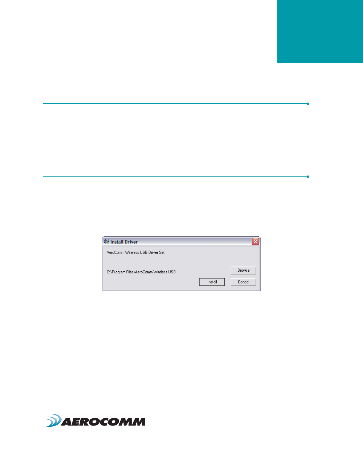
install the software, run Setup.exe and follow the installation prompts. During the installation, the software will prompt
the user to install the Aerocomm USB Driver. It is recommended that the user installs the driver at the same time as
the software.
Note: The USB driver is only required for Aerocomm devices with a USB interface and is not required by the
ConnexNet transceiver.
The installer will notify the user when the software has successfully been installed. The user may be prompted to
reboot the PC to complete the installation.
Click OK to complete the installation. By default, the software is stored in the following location on the Start Menu:
Start -> All Programs -> Aerocomm Wireless, Inc. -> Aerocomm OEM.exe
Tabla de contenidos
Manuales populares de Hardware de red de otras marcas

Matrix Switch Corporation
Matrix Switch Corporation MSC-HD161DEL Manual de usuario

B&B Electronics
B&B Electronics ZXT9-IO-222R2 Manual de usuario

Yudor
Yudor YDS-16 Manual de usuario

D-Link
D-Link ShareCenter DNS-320L Manual de usuario

Samsung
Samsung ES1642dc Instrucciones de uso

Honeywell Home
Honeywell Home LTEM-PV Instrucciones de montaje


