AEMC AX501 Manual de usuario

DC POWER SUPPLY AX501
AX502
AX503
ENGLISH User Manual
IEC 61010-1
POWER
ON
OFF
AX 501
8.8.8.
VOLTAGE
8.8.8.
CURRENT
100V
CAT I
VA
30V LIMIT
0
COARSEFINE
2.5A
0
IEC 61010-1
POWER
ON
OFF
AX 503
8.8.8. 8.8.8. 8.8.8. 8.8.8.
MASTER
TRACKING
SLAVE
100V
CAT I
100V
CAT I
100V
CAT I
AV AVV
2.5A
30V
3V
5V
2.7V 5.5V
LIMIT 5ALIMIT LIMIT
ON
0
0
COARSEFINE FINE
2.5A
30V
0
0
COARSE
www.ShopAEMC.com
Shop for AEMC products online at: 1.888.610.7664

Statement of Compliance
Chauvin Arnoux®, Inc. d.b.a. AEMC®Instruments
certifies that this instrument has been calibrated
using standards and instruments traceable to
international standards.
We guarantee that at the time of shipping your
instrument has met its published specifications.
An NIST traceable certificate may be
requested at the time of purchase, or obtained
by returning the instrument to our repair and
calibration facility, for a nominal charge.
The recommended calibration interval for this
instrument is 12 months and begins on the date of
receipt by the customer. For recalibration, please
use our calibration services. Refer to our repair
and calibration section at .
Serial #: ________________________________
Catalog #: 2130.05 / 2130.06 / 2130.07
Model #: AX501 / AX502 / AX503
Please fill in the appropriate date as indicated:
Date Received: _________________________________
Date Calibration Due: _______________________
www.ShopAEMC.com
Shop for AEMC products online at: 1.888.610.7664

Table of Contents
1. INTRODUCTION............................................................................... 3
1.1 International Electrical Symbols................................................3
1.2 DenitionofMeasurementCategories .....................................4
1.3 ReceivingYourShipment..........................................................4
1.4 OrderingInformation.................................................................4
1.4.1 Accessories ..................................................................4
2. PRODUCT FEATURES ...................................................................... 5
2.1 Description................................................................................5
2.2 ControlFeatures .......................................................................6
2.2.1 ModelAX501 ................................................................6
2.2.2 ModelAX502 ................................................................7
2.2.3 ModelAX503 ................................................................8
2.3 ControlDescriptions .................................................................9
2.3.1 PowerOn/OButton.....................................................9
2.3.2 VoltageandCurrentAdjustments .................................9
2.3.3 Current“LIMIT”LED .....................................................9
2.3.4 “TRACKING”Switch(ModelsAX502andAX503).........10
2.3.5 Setting“TRACKING”...................................................10
2.3.6 Digital“LED”displays ................................................. 11
2.3.7 OutputTerminals......................................................... 11
2.3.8 GroundTerminal .........................................................11
2.4 PowerSupply.......................................................................... 11
3. SPECIFICATIONS........................................................................... 12
3.1 SpecicationChart..................................................................12
3.2 GeneralSpecications............................................................13
3.3 SafetySpecications ..............................................................14
4. OPERATION .................................................................................. 15
4.1 BeforeUsingtheInstrument ...................................................15
4.2 OperatingInstructions.............................................................15
4.2.1 UsingIndependentOutputs ........................................16
4.2.2 Useof2OutputsinParallel(AX502andAX503) .......16
www.ShopAEMC.com
Shop for AEMC products online at: 1.888.610.7664

4.2.3 Useof2OutputsinSeries(AX502andAX503) .........17
4.2.4 Useof2.7Vto5.5V(5A)PowerSupply(AX503Only) ...18
5. MAINTENANCE ............................................................................. 19
5.1 Warning...................................................................................19
5.2 FuseReplacement..................................................................19
5.3 Cleaning..................................................................................19
5.4 Storage ...................................................................................19
RepairandCalibration...........................................................................20
TechnicalandSalesAssistance ............................................................20
Limited Warranty ...................................................................................21
WarrantyRepairs...................................................................................21
www.ShopAEMC.com
Shop for AEMC products online at: 1.888.610.7664
DC Power Supply Models AX501, AX502 and AX503
3
CHAPTER 1
INTRODUCTION
WARNING
Thesesafetywarningsareprovidedtoensurethesafetyofpersonnel
andproperoperationoftheinstrument.
• Readthisusermanualcompletelyandfollowallthesafetyinformation
beforeattemptingtouseorservicethisinstrument.
• Use caution on any circuit: Potentially high voltages and currents
maybepresentandmayposeashockhazard.
• Onlyuseleadswiththeproperrating.Alwaysinspecttheinstrument
andleadpriortouse.Replaceanydefectivepartsimmediately.
• Safetyistheresponsibilityoftheoperator!
• Anydefectiveleadinsulation,insideoroutsideoftheinstrument,or
disconnectionoftheprotectiveearth/groundterminalmaymakethe
instrumentdangerous.
• The plug should only be inserted into a socket equipped with a
grounding contact. The safety connection must not be broken by
useofanextensionleadwithoutprotectiveinsulation.
• Beforeconnectingthepowersupply,makesurethedistributionnet-
workis115VAC±10%.
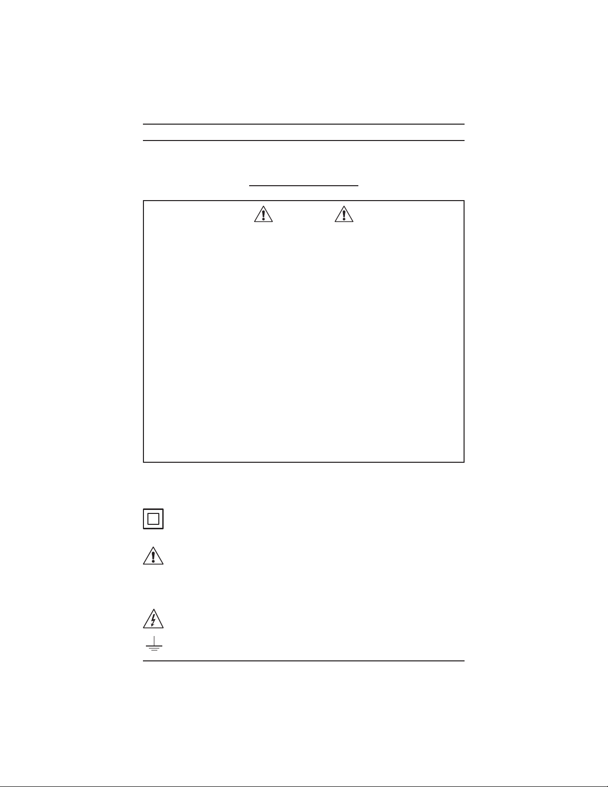
1.1 International Electrical Symbols
Thissymbolsigniesthattheinstrumentisprotectedbydoubleor
reinforcedinsulation.Useonlyspeciedreplacementpartswhen
servicingtheinstrument.
This symbol on the instrument indicates a WARNING and that
theoperatormustrefertotheusermanualforinstructionsbefore
operating the instrument. In this manual, the symbol preceding
instructions indicates that if the instructions are not followed,
bodilyinjury,installation/sampleandproductdamagemayresult.
Riskofelectricshock.Thevoltageatthepartsmarkedwiththis
symbolmaybedangerous.
Earth/Ground
www.ShopAEMC.com
Shop for AEMC products online at: 1.888.610.7664

4
DC Power Supply Models AX501, AX502 and AX503
1.2 Definition of Measurement Categories
CAT II: For measurements performed on circuits directly connected to
the electrical distribution system. Examples are measurements
onhouseholdappliancesorportabletools.
CAT III: For measurements performed in the building installation at
the distribution level such as on hardwired equipment in xed
installationandcircuitbreakers.
CAT IV: For measurements performed at the primary electrical supply
(<1000V) such as on primary overcurrent protection devices,
ripplecontrolunits,ormeters.
1.3 Receiving Your Shipment
Uponreceivingyourshipment,makesurethatthecontentsareconsistent
withthepackinglist.Notifyyourdistributorofanymissingitems.Iftheequip-
mentappearstobedamaged,leaclaimimmediatelywiththecarrierand
notifyyourdistributoratonce,givingadetaileddescriptionofanydamage.
Savethedamagedpackingcontainertosubstantiateyourclaim.
1.4 Ordering Information
DCPowerSupplyModelAX501.......................................... Cat. #2130.05
(Single output, 0 to 2.5A; 0 to 30VDC)
DCPowerSupplyModelAX502.......................................... Cat. #2130.06
(Dual output, 0 to 2.5A; 0 to 30VDC; 110V, 60Hz, US plug)
DCPowerSupplyModelAX503.......................................... Cat. #2130.07
(Triple output, two 0 to 2.5A; 0 to 30VDC; 5A; 2.7 to 5.5VDC;
110V, 60Hz, US plug)
1.4.1 Accessories
LeadSet(2color-codedleads,1groundlead,
2alligatorclipsand2gripprobes)....................................... Cat. #2117.78
Setof5Fuses10A/250V,5x20mmSlowBlow ................... Cat. #2118.83
www.ShopAEMC.com
Shop for AEMC products online at: 1.888.610.7664

DC Power Supply Models AX501, AX502 and AX503
5
CHAPTER 2
PRODUCT FEATURES
2.1 Description
Thiscomprehensiverangeof linear power supplies with digital displays
is designed to meet the requirements of educational establishments,
laboratories,productiontestsandmaintenancedepartments.
Itoersahighlevelofoperating safetyby guaranteed insulation of the
outputs from the mains when used at an extra low safety voltage, a
comprehensiveprotectionsystemandexcellentergonomics.
The quality of the signal delivered, the precision of the display and the
robustnessofthehousingmakethemtop-levellaboratoryinstruments.
The AX501 oers:
• Singleoutput
• Simultaneousdisplayoftheoutputvoltageandcurrent
• Voltageadjustablefrom0to30Vforavariablecurrentof
0to2.5A(75W)
The AX502 oers:
• Dualoutput
• Simultaneousdisplayoftheoutputvoltageandcurrentforeach
output
• Two0to30V,0to2.5A(150Wmax)outputs;connectedinseries,
parallelorcoupled,(trackingfunction)±30V
The AX503 oers:
• Triplepowersupply
• Simultaneousdisplayoftheoutputvoltageandcurrentforeach
0-30Voutput
• Two0to30V,0to2.5A(150Wmax)outputs;connectedinseries,
parallelorcoupled,(trackingfunction)±30V
• Anadjustable2.7to5.5V,5Axedoutputforsupplyinglogiccir-
cuitsat3Vor5V
www.ShopAEMC.com
Shop for AEMC products online at: 1.888.610.7664

6
DC Power Supply Models AX501, AX502 and AX503
2.2 Control Features
2.2.1 Model AX501
2
4
5678
1
9
10
3
Figure 1
1. Voltagedisplay(green)
2. Currentdisplay(red)
3. CurrentlimitLED
4. PowerOn/Obutton
5. Finevoltageadjustmentpotentiometer
6. Outputterminal(+)
7. Outputterminal(-)
8. Coarsevoltageadjustmentpotentiometer
9. Currentlimitadjustmentpotentiometer
10. Groundterminal()
www.ShopAEMC.com
Shop for AEMC products online at: 1.888.610.7664

DC Power Supply Models AX501, AX502 and AX503
7
2.2.2 Model AX502
1
7
6
8
910 11
1
3
2
2 3
4 5
612
910 11
8
Figure 2
1. Currentdisplay(red)
2. CurrentlimitLED
3. Voltagedisplay(green)
4. TrackingfunctionLED
5. TrackingOn/Oswitch
6. Currentlimitadjustmentpotentiometer
7. PowerOn/Obutton
8. Finevoltageadjustmentpotentiometer
9. Outputterminals(+)
10. Outputterminals(-)
11. Coarsevoltageadjustmentpotentiometer
12. Groundterminal()
www.ShopAEMC.com
Shop for AEMC products online at: 1.888.610.7664

8
DC Power Supply Models AX501, AX502 and AX503
2.2.3 Model AX503
10
9
12
1
7
6
8
9
10 11
1
3
2
2 3
4 5
6
1413
9
10 11
8
Figure 3
1. Currentdisplay(red)
2. CurrentlimitLED
3. Voltagedisplay(green)
4. TrackingfunctionLED
5. TrackingOn/Oswitch
6. Currentlimitadjustmentpotentiometer
7. PowerOn/Obutton
8. Finevoltageadjustmentpotentiometer
9. Outputterminals(+)
10. Outputterminals(-)
11. Coarsevoltageadjustmentpotentiometer
12. Voltageadjustmentpotentiometer
13. 5AcurrentlimitLED
14. Groundterminal()
www.ShopAEMC.com
Shop for AEMC products online at: 1.888.610.7664
Otros manuales para AX501
2
Este manual sirve para los siguientes modelos
2
Tabla de contenidos
Otros manuales de Fuente de alimentación de AEMC


