ADDC BioDigitalPC SR-60 Manual de usuario

SR-60
USER GUIDE
PLUG INTO THE FUTURE OF TECHNOLOGY

2
Revision History
Revision Notes
V2.5 Revision 2.5 was published in
November of 2017.

3
Table of Contents
Section 1 Receiving Your SR-60 5
Section 1.1 What's in the Box? 5
Section 2 SR-60 Preparaon 6
Section 2.1 Preparing For Your SR-60 6
Section 2.2 Installing Your SR-60 into a Rack 7
Section 2.3 Installing Your BioDigitalPC®s9
Section 2.4 SR-60 Power Supplies 11
Section 2.5 Networking Your SR-60 12
Section 2.6 Powering On Your SR-60 13
Section 3 SR-60 Overview 14
Section 3.1 SR-10 Modules 15
Section 3.2 Rear Panel 16
Section 3.3 Front Panel 17
Section 4 ROMWare Soware 18
Section 4.1 Login 18
Section 4.2 Main Screen Overview 18
Section 4.3 AC Power Monitoring 19
Section 4.4 DC Power Control & Monitoring 20
Section 4.5 SR-10 Switch Conguraon 21
Section 4.6 BioDigitalPC® Power Contol and
Monitoring
22
Section 4.7 SR-10 Switch Serial Interface 25
Appendix A Tesng Your SR-60 27
Appendix B A Successful SR-60 Component Test 28

4
Notes, Important Information & Warnings
This manual details installation of the chasis, the components inside of the chassis, and notable
features of the SR-60 server solution.
Installations will be supported by ADDC. Unless otherwise specied, all instructions provided in this
manual will assume that a user is a trained technician.
How to Read this Document
You will see this icon throughout the manual intended to point out warnings, important information,
and briey explain any new terminology.

5
Equipment (Not Included)
• Laptop or Testing Network
• 5/32" Allen Key (Optional)
Equipment (Included)
• SR-60 Chassis
• SR-60 Top Cover [Comes Assembled]
• BioDigitalPC®Server Cards [Check
Invoice for Quantity]
• 4 AC/DC Power Supplies
• 12 10Gbps SFP+ Cables
• 4 AC Power Cords
• 2 Rack Slides
Section 1.1 - What's in the Box?
10Gbps SFP+ Cables
SR-60 Chassis
SR-60 Top Cover
Rack Slides
AC/DC Power Supplies
AC Power Cords
Section 1.0 - Recieving Your SR-60

6
When installing the SR-60 into a rack, the selected location should meet environmental standards as
described below.
Rack Space and Airflow Considerations
To allow for adequate airow, technicians should observe the following space and airow requirements
when deciding where to install a rack.
• Leave a minimum clearance of 36in (91.4cm) in front of the rack.
• Leave a minimum clearance of 20in (50.8cm) behind the rack.
Temperature Considerations
Your SR-60 is designed to operate at room temperature with its self-contained cooling.
Power Considerations
When properly congured and installed the SR-60 can draw up to 2kW depending on the number, load,
and version of the BioDigitalPC®s used.
To prevent improper cooling of equipment, do not block the fans.
Section 2.1 - Preparing For Your SR-60
If using the dual feed redundant power solution (See Section 2.6.2), each power source must be
capable of supporting a maximum draw of 2kW.
Section 2 - SR-60 Preparation
7
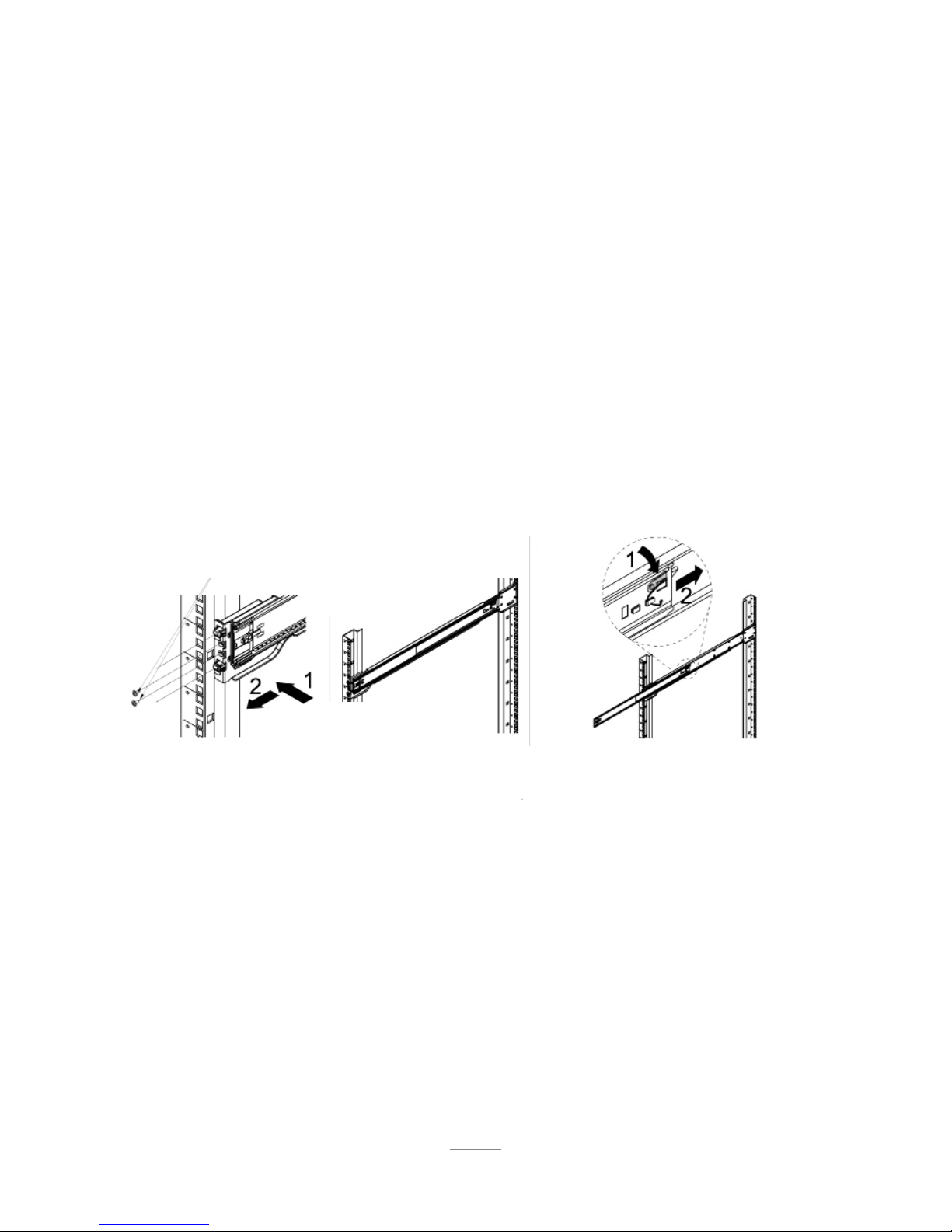
Section 2.2 - Installing Your SR-60 into a Rack
A. B.
The chassis package includes two rail assemblies in the rack mounting kit. Each assembly consists of
two sections: an inner xed chassis rail that secures directly to the server chassis and an outer xed
rack rail that secures directly to the rack itself.
Press the lever to
extend the outer rails.
Stability hazard. The rack stabilizing mechanism must be in place, or the rack must be bolted to the
oor before you slide the unit out for servicing. Failure to stabilize the rack can cause the rack to tip
over and cause severe injury to the technicians and damage to the device.
This section provides information on installing the SR-60 chassis into a rack unit with the quick-release
rails provided.
C.
Repeat step A to mount
all four corners.
Hang the hooks of the rails
into rack holes. Screw the
rails in if necessary.
Make sure the ball shuttle is
at the very front.
Inner and outer chassis rails are shipped together, before continuing please seperate outer rail from
inner rail.

8
D. Align the inner rails into the extended outer rails and push the chassis to the rear of the rack.
Optional: Screw the
handles to the rack.
(Top Cover not shown)
Section 2.2 - Installing Your SR-60 into a Rack

9
Section 2.3 - Installing Your BioDigitalPC®s
BioDigitalPC®s are hot-pluggable, meaning technicians do not need to remove power to begin adding or
removing them.
Section 2.3.1 - Removing the SR-60 Top Cover:
In order to add or remove BioDigitalPC®s the SR-60 chassis can be pulled out of the rack, or the SR-60's
Top Cover needs to be removed temporarily.
SR-60 system can be running while installing new server cards.
Only trained technicians are authorized to work beneath the SR-60 System Cover and access any of
the components inside the system.
Section 2.3.2 - Installing a BioDigitalPC®
Step 3: Insert Card with
"Arnouse Digital Devices
Corp." facing upwards
and the connector of the
card is facing towards the
latch. When inserting the
card place between the
two horizontal metal bars,
ensuring the card is going
to be aligned properly.
Step 4: Once the card
is in between the two
horizonal bars, locate
the small locking tab and
push it in towards the
card. The card should
now be locked into place.
Fully inserted card
Step 1: Make
sure the latch is
perpendicular to
the system cover.
Step 2: Make sure
locking tab is unlocked.
small
locking tab
latch

10
Step 1: Find the
locking tab located
to the right of the
card slot.
Unlock the locking
tab.
Section 2.3.4 - Replacing the SR-60 Top Cover
Section 2.3.3 - Removing a BioDigitalPC®
Section 2.3 - Installing Your BioDigitalPC®s
Step 1: Insert Card with "Arnouse
Digital Devices Corp." facing
upwards and the connector of
the card is facing towards the
left. When inserting the card
place between the two horizontal
metal bars, insuring the card is
going to be aligned properly.
Step 2: Once the card is in
between the two horizonal bars,
locate the small locking tab and
push it in towards the card. The
card should now be locked into
place.
Once complete, a technician should
replace the SR-60 Top Cover.
Step 3: Reset the ejection bar to the original
position to make the card removal easier.
Step 2: Pull the
ejection bar forward
towards you, you
should feel the
card pop out of the
connector.
Tabla de contenidos


