Adaptec Snap Server 700i Series Manual de usuario

Field Service Documentation 1
Snap Server 700i Series
Copyright © 2007, Adaptec, Inc. All rights reserved. Information in this document is subject to change without notice and does not represent
a commitment on the part of Adaptec or any of its subsidiaries.
Upgrading to a Second Power Supply Module
Caution There are static-sensitive electronics inside the unit. Before you handle any
parts, make sure you are working at a static-controlled workstation and that you are
properly grounded.
Shutting Down the Server
Caution Shut down the server before you make any repairs. Improper shutdown may
lead to physical harm or loss of data.
1To start the shutdown process, push the power
button on the front of the server.
The system LED blinks 3 times per second and
the green power LED remains lit until the
shutdown process is complete. Do not disconnect
the AC power cord while the power LED remains
lit.
2After the power LED is off, disconnect the AC
power cord and all other cables from the back of the server.
3The server is heavy. With the help of another person, remove the server from the
rack to a clean surface with ample room to the front and rear. See the FRU
procedure Installing the Snap Server in a Rack for instructions on removing the
server from the rack.
Removing the Top Cover
1To release the cover, first remove the Phillips screw on the right side of the server
(see illustration).
Power
Upgrading to a Second Power Supply Module Snap Server 700i Series
2Field Service Documentation
Copyright © 2007, Adaptec, Inc. All rights reserved. Information in this document is subject to change without notice and does not represent
a commitment on the part of Adaptec or any of its subsidiaries.
2With both thumbs, press the buttons on the top of the cover, then slide the cover
off of the rear of the server and set it aside.
Installing a Second Power Supply Module
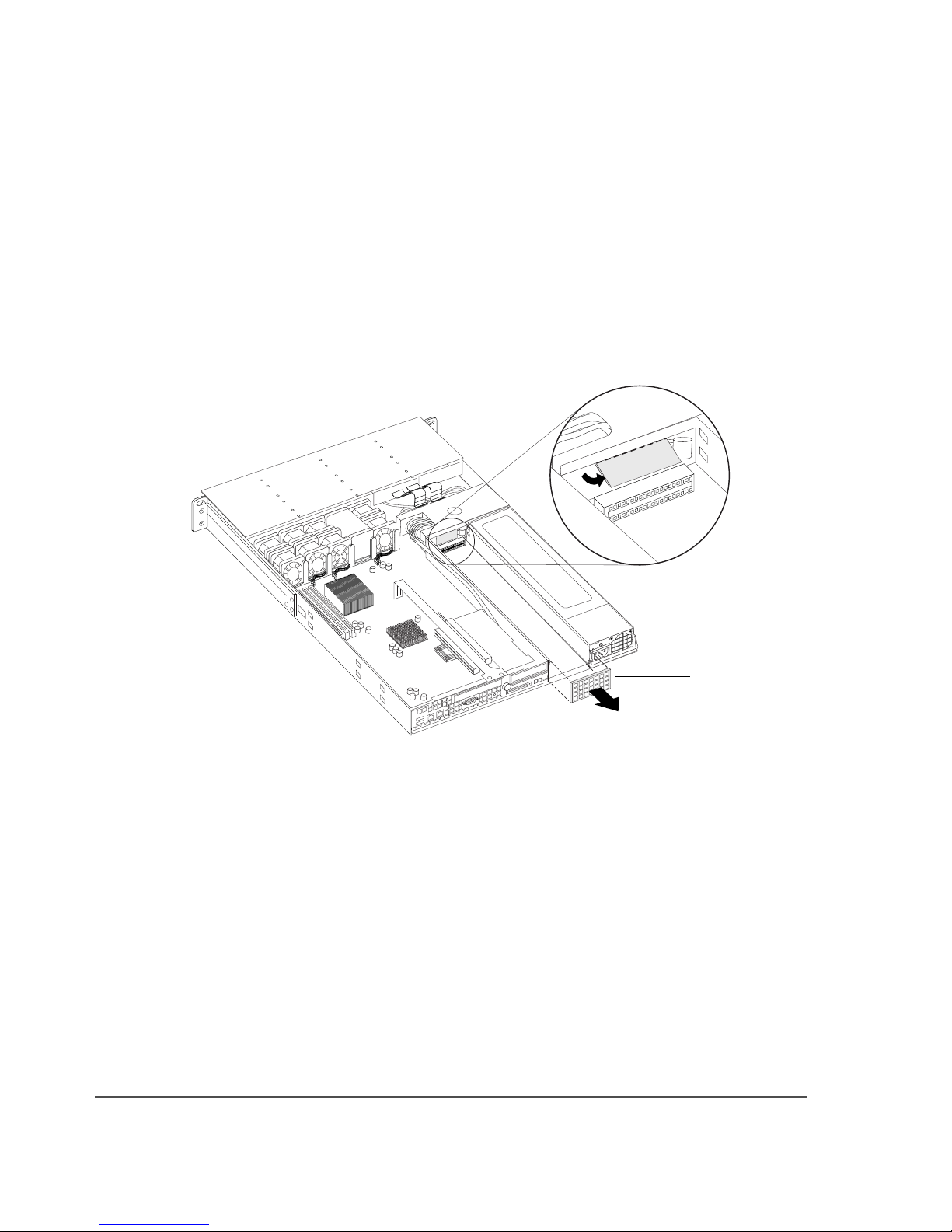
1The electrical connectors for a second power supply are protected by a piece of
metal. Take a screwdriver or other tool and break off the plastic covering (see
illustration). Also remove the vented cover on the rear of the unit, covering the
opening for the second power supply.
2Install the second power supply by resting the body of the module in one hand
while holding the handle with the other and inserting the module. Slide it firmly
Vented cover

Field Service Documentation 3
Copyright © 2007, Adaptec, Inc. All rights reserved. Information in this document is subject to change without notice and does not represent
a commitment on the part of Adaptec or any of its subsidiaries.
Snap Server 700i Series Upgrading to a Second Power Supply Module
into place, making sure it is seated all the way into the chassis. The latch will click
in to indicate when it is locked.
3You can now replace the top cover. Lower the cover onto the server, pushing it
forward from the rear of the server until it is firmly seated, and replace the screw
on the right side of the server.
4Fold the handle down against the module.
Restoring Power to the Server
1If you removed the server from the rack, replace it now with the help of another
person.
2Reattach all cables to the rear of the server.
3Press the power button on the front of the server.

Field Service Documentation 1
Snap Server 700i Series
Copyright © 2007, Adaptec, Inc. All rights reserved. Information in this document is subject to change without notice and does not represent
a commitment on the part of Adaptec or any of its subsidiaries.
Replacing a Power Supply Module
Caution There are static-sensitive electronics inside the unit. Before you handle any
parts, make sure you are working at a static-controlled workstation and that you are
properly grounded.
Shutting Down the Server
Caution Shut down the server before you make any repairs. Improper shutdown may
lead to physical harm or loss of data.
Note If your server has dual power supplies, you do not need to shut down the
server.
1To start the shutdown process, push the power
button on the front of the server.
The system LED blinks 3 times per second and
the green power LED remains lit until the
shutdown process is complete. Do not disconnect
the AC power cord while the power LED remains
lit.
2After the power LED is off, disconnect the AC
power cord and all other cables from the back of the server.
3The server is heavy. With the help of another person, remove the server from the
rack to a clean surface with ample room to the front and rear. See the FRU
procedure Installing the Snap Server in a Rack for instructions on removing the
server from the rack.
Removing a Failed Power Supply Module
1From the rear of the server, observe the LED on the power supply module. On a
failed module, the LED will be amber, blinking green, or off.
2Remove the power cord from the failed module.
Note If you have a dual power supply, the system may sound an alarm when the
power cord from the failed module is removed. Removing the power supply will
stop the alarm.
Power

Replacing a Power Supply Module Snap Server 700i Series
2Field Service Documentation
Copyright © 2007, Adaptec, Inc. All rights reserved. Information in this document is subject to change without notice and does not represent
a commitment on the part of Adaptec or any of its subsidiaries.
3To release the module, pull the handle up, push the red latch to the right, and
then pull the handle towards you.
4Grasp the handle and pull the module out of the chassis, catching the body of the
module in the other hand, and set it aside.
Inserting a Replacement Power Supply Module
1Resting the body of the module in one hand while holding the handle with the
other, insert the module and slide firmly into place. Make sure it is seated all the
way into the chassis.
2The latch will lock the module into place. Fold the handle down against the
module.
3Insert the power cord and connect to a power source. The LED should be solid
green.
Note If you have a dual power supply and do not immediately insert the power
cord and connect it to a power source, an alarm will sound until you do.
Release latch

Field Service Documentation 1
Snap Server 700i Series
Copyright © 2007, Adaptec, Inc. All rights reserved. Information in this document is subject to change without notice and does not represent
a commitment on the part of Adaptec or any of its subsidiaries.
Replacing a PCI Card
Caution There are static-sensitive electronics inside the unit. Before you handle any
parts, make sure you are working at a static-controlled workstation and that you are
properly grounded.
Two PCI cards can be replaced in the Snap Server 700i Series:
• SAS HBA
•EthernetNIC
Shutting Down the Server
Caution Shut down the server before you make any repairs. Improper shutdown may
lead to physical harm or loss of data.
1To start the shutdown process, push the power
button on the front of the server.
The system LED blinks 3 times per second and the
green power LED remains lit until the shutdown
process is complete. Do not disconnect the AC
power cord while the power LED remains lit.
2After the power LED is off, disconnect the AC
power cord and all other cables from the back of the server.
3The server is heavy. With the help of another person, remove the server from the
rack to a clean surface with ample room to the front and rear. See the FRU
procedure Installing the Snap Server in a Rack for instructions on removing the
server from the rack.
Power

Replacing a PCI Card Snap Server 700i Series
2Field Service Documentation
Copyright © 2007, Adaptec, Inc. All rights reserved. Information in this document is subject to change without notice and does not represent
a commitment on the part of Adaptec or any of its subsidiaries.
Removing the Top Cover
1To release the cover, first remove the Phillips screw on the right side of the server
(see illustration).
2With both thumbs, press the buttons on the top of the cover, then slide the cover
off of the rear of the server and set it aside.

Field Service Documentation 3
Copyright © 2007, Adaptec, Inc. All rights reserved. Information in this document is subject to change without notice and does not represent
a commitment on the part of Adaptec or any of its subsidiaries.
Snap Server 700i Series Replacing a PCI Card
Releasing the PCI Riser
Two thumbscrews hold the expansion cage in place, one on the rear of the chassis
and the other on the motherboard (see illustration). Loosen the thumbscrews (you
may need to use a screwdriver).
Replacing a SAS HBA
1Carefully lift the riser but do not pull the SAS cable attached to the SAS card.
Invert the cage to expose the SAS connector on the card. Squeeze the buttons on
either side of the SAS cable connector and remove the cable.
2Unscrew the bracket, grasp the old card firmly, and pull it out of the PCI slot.
3Insert the new card, snap it in place, and screw in the PCI card bracket.
Thumbscrews

Replacing a PCI Card Snap Server 700i Series
4Field Service Documentation
Copyright © 2007, Adaptec, Inc. All rights reserved. Information in this document is subject to change without notice and does not represent
a commitment on the part of Adaptec or any of its subsidiaries.
4Connect the SAS cable to the card.
5Replace the expansion cage in the chassis and tighten the two thumbscrews.
Replacing an Ethernet Card
1Once you have removed the expansion cage from the chassis, insert the NIC into
the appropriate PCI slot, snap it in place, and screw in the PCI card bracket.
2Replace the expansion cage in the chassis and tighten the two thumbscrews.
Replacing the Top Cover
Be sure to replace the top cover. Do not operate the server if the cover is not in place.
1Lower the top cover onto the server.
2From the rear of the server, push the cover forward until it is firmly seated.
3Replace the screw on the right side of the server.
Restoring Power to the Server
1If you removed the server from the rack, replace it now with the help of another
person.
2Reattach all cables to the rear of the server.
3Push the power button on the front of the server to boot up the server.
NIC PCI slot

Field Service Documentation 1
Snap Server 700i Series
Copyright © 2007, Adaptec, Inc. All rights reserved. Information in this document is subject to change without notice and does not represent
a commitment on the part of Adaptec or any of its subsidiaries.
Replacing the Front Bezel
Removing the Front Bezel
1Press the latches, one on each side of the front bezel.
2Still holding the latches in the release position, pull the bezel away from the
chassis.
Replacing the Front Bezel
1Position the new bezel so the tabs line up to slide under the top edge of the cover.
Make sure the LED/LCD connector on the bezel matches up with the connector
on the chassis.
2Press firmly to attach the bezel. A muted click indicates the latches are locked.
Otros manuales para Snap Server 700i Series
2
Tabla de contenidos
Otros manuales de Servidor de Adaptec


