AccuEnergy AcuLink 810 Manual de usuario

AcuLink 810
Data Acquisition Server
User's Manual
www. .com information@itm.com1.800.561.8187

V: 1.0 Revised: May. 2019
II
Copyright © 2019 V1.00
This manual may not be altered or reproduced in whole or in part by any means
without the expressed written consent of Accuenergy.
www. .com information@itm.com1.800.561.8187

V: 1.0 Revised: May. 2019
1
The information contained in this document is believed to be accurate at the time
of publication, however, Accuenergy assumes no responsibility for any errors which may
appear here and reserves the right to make changes without notice. Please ask the local
representative for latest product specications before ordering.
Please read this manual carefully before installation, operation and maintenance of the
AcuLink810 series meter. The following symbols in this manual are used to provide warning of
danger or risk during the installation and operation of the meters.
Electric Shock Symbol: Carries information about procedures which must be
followed to reduce the risk of electric shock and danger to personal health.
Safety Alert Symbol: Carries information about circumstances which if not
considered may result in injury or death.
Prior to maintenance and repair, the equipment must be de-energized and grounded. All
maintenance work must be performed by qualied, competent accredited professionals who
have received formal training and have experience with high voltage and current devices.
Accuenergy shall not be responsible or liable for any damages or injuries caused by improper
meter installation and/or operation.
www. .com information@itm.com1.800.561.8187

V: 1.0 Revised: May. 2019
2
Table of Contents
1. Overview .............................................................................................................4
2. Functional Description......................................................................................4
2.1 Hardware Specications.............................................................................................. 4
2.2 Power ............................................................................................................................. 4
2.3 Communication ............................................................................................................ 5
2.4 Inputs ............................................................................................................................. 5
2.5 Environment ................................................................................................................. 5
3. Appearance and Dimensions ...........................................................................6
4. Installation..........................................................................................................7
4.1 Installation Checklist .................................................................................................... 7
4.2 Hardware installation................................................................................................... 8
4.2.1 Powering the unit .............................................................................................. 8
4.2.2 RS485 Network .................................................................................................. 9
4.2.3 Digital Input Setup...........................................................................................10
5. Initializing the AcuLink 810.............................................................................11
5.1 Accessing the AcuLink 810 Web Interface ...............................................................11
5.1.1 Method 1 - Direct Connection via Ethernet..................................................11
5.1.2 Method 2 - Using WIFI to connect to the Meters Web Interface ...............16
6. AcuLink 810 User Interface.............................................................................18
6.1 Modbus Template ......................................................................................................18
6.2 Adding Devices to the AcuLink 810 ..........................................................................20
6.2.1 Modbus-TCP/IP ................................................................................................23
6.2.2 Modbus-RTU ....................................................................................................23
6.2.3 Modbus Gateway Function ............................................................................26
Adding Modbus Gateway Device ............................................................ 26
6.3 Viewing Data of Modbus Devices ............................................................................27
6.3.1 Conguration ...................................................................................................29
6.4 Deleting Modbus Devices from AcuLink 810 ..........................................................30
www. .com information@itm.com1.800.561.8187

V: 1.0 Revised: May. 2019
3
6.5 Alarms ..........................................................................................................................31
6.5.1 How to create alarm.......................................................................................31
6.5.2 How to view alarm........................................................................................... 32
6.6 Digital Inputs ...............................................................................................................33
6.7 Logs .............................................................................................................................. 35
6.7.1 Alarm Logs........................................................................................................ 35
6.7.2 Event Logs ........................................................................................................ 36
6.8 System Settings...........................................................................................................36
6.9 Date & Time.................................................................................................................37
6.10 Network Settings ...................................................................................................... 38
6.10.1 WIFI .................................................................................................................38
6.10.2 Ethernet 1....................................................................................................... 40
6.10.3 Ethernet 2....................................................................................................... 41
6.11 Email (SMTP)..............................................................................................................42
6.12 Alarm Notication .................................................................................................... 43
6.13 Post Channels ..........................................................................................................43
6.13.1 HTTP Post Method ........................................................................................43
6.13.2 FTP Post Method ...........................................................................................44
6.14 Data Logging ............................................................................................................. 45
6.15 AcuCloud ...................................................................................................................47
6.16 Data Management.................................................................................................... 51
6.16.1 Download Data..............................................................................................51
Delete Data ................................................................................................ 51
6.16.2 Users Password ....................................................................................................52
6.16.3 Firmware Update...................................................................................................52
Manual Firmware Update ........................................................................53
Remote Firmware Update........................................................................54
6.17 Network Diagnostics ................................................................................................57
7. LED Description................................................................................................61
7.1 AcuMesh LEDs............................................................................................................. 61
7.2 WiFi LEDs .....................................................................................................................62
7.3 RS485 LEDs.................................................................................................................. 62
8. Reset Button.....................................................................................................63
www. .com information@itm.com1.800.561.8187

AcuLink 810 Data Aquisition Server
V: 1.0 Revised: May. 2019
4
1. Overview
The AcuLink 810 is an intelligent data acquisition server and gateway that allows users to
collect data from all Accuenergy meters, sensors and other third party devices.
The AcuLink collects and logs time-stamped data from connected downstream devices (se-
rial or Ethernet), and is able to store this data locally in non volatile memory. When using
Ethernet it is possible to push or pull data using HTTP or FTP protocols as well as pushing
data to dierent web-based energy management systems or any front end software plat-
form. There is no software required for the AcuLink as all conguration is done from the
gateways web interface.
2. Functional Description
2.1 Hardware Specications
• Disk Capacity: 8 GB RAM
• Interval Recording: 1-1440 minutes, user selectable
• LEDs: Power, Ethernet, WiFi, Modbus TX/RX, AcuMesh
2.2 Power
Power Supply: 24VDC, 500mA
NOTE: This unit is to be sourced by a Class 2 power supply with the following output:
24VDC, 500mA min not to exceed 8A.
Isolation: RJ45 Ethernet 1500Vrms
RS485 2500Vrms
Digital Input 5000Vrms
www. .com information@itm.com1.800.561.8187

5
V: 1.0 Revised: May. 2019
AcuLink 810 Data Aquisition Server
2.3 Communication
• Protocols Supported: Modbus RTU, Modbus TCP, HTTP/HTTPS, FTP, SNTP, SMTP
• LAN: 2 x RJ45 10/100 Ethernet, full half duplex, auto polarity
• WIFI: 802.11 b/g/n, 2.4GHz
• USB: USB expansion port, USB 2.0 Host
2.4 Inputs
Serial Port: RS485 Modbus, supports up to 32 external devices (expandable)
Baud Rate: 9600-115200 bps
Digital Input: 8 pulse counters
Input Voltage Range: 8-28Vdc
Input Current (Max): 8mA
Start Voltage: 15V
Stop Voltage: 5V
Pulse Frequency (Max): 100Hz, 50% Duty Ratio (5ms ON and 5ms OFF)
2.5 Environment
• North America: -25 to 70 degrees Celsius, 90% RH, non-condensing
www. .com information@itm.com1.800.561.8187
V: 1.0 Revised: May. 2019
6
Chapter 3: Appearance & Dimensions
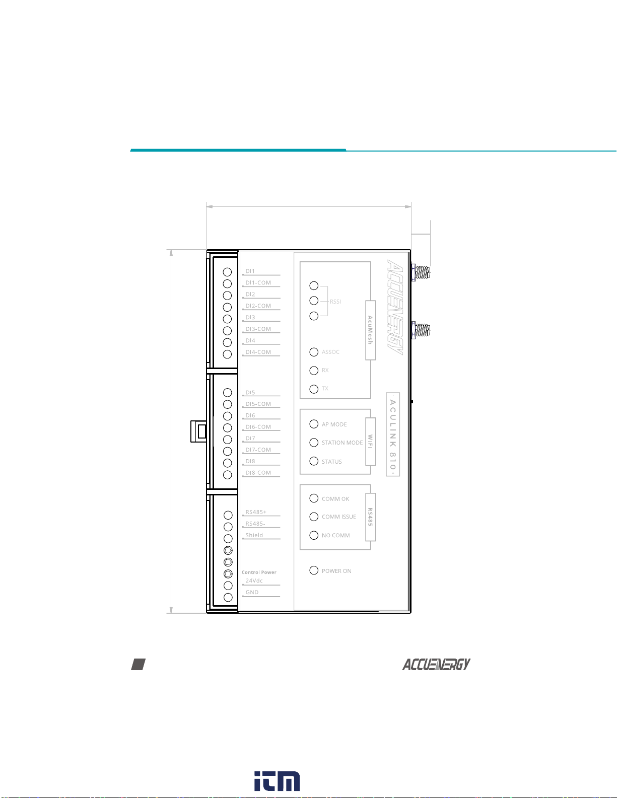
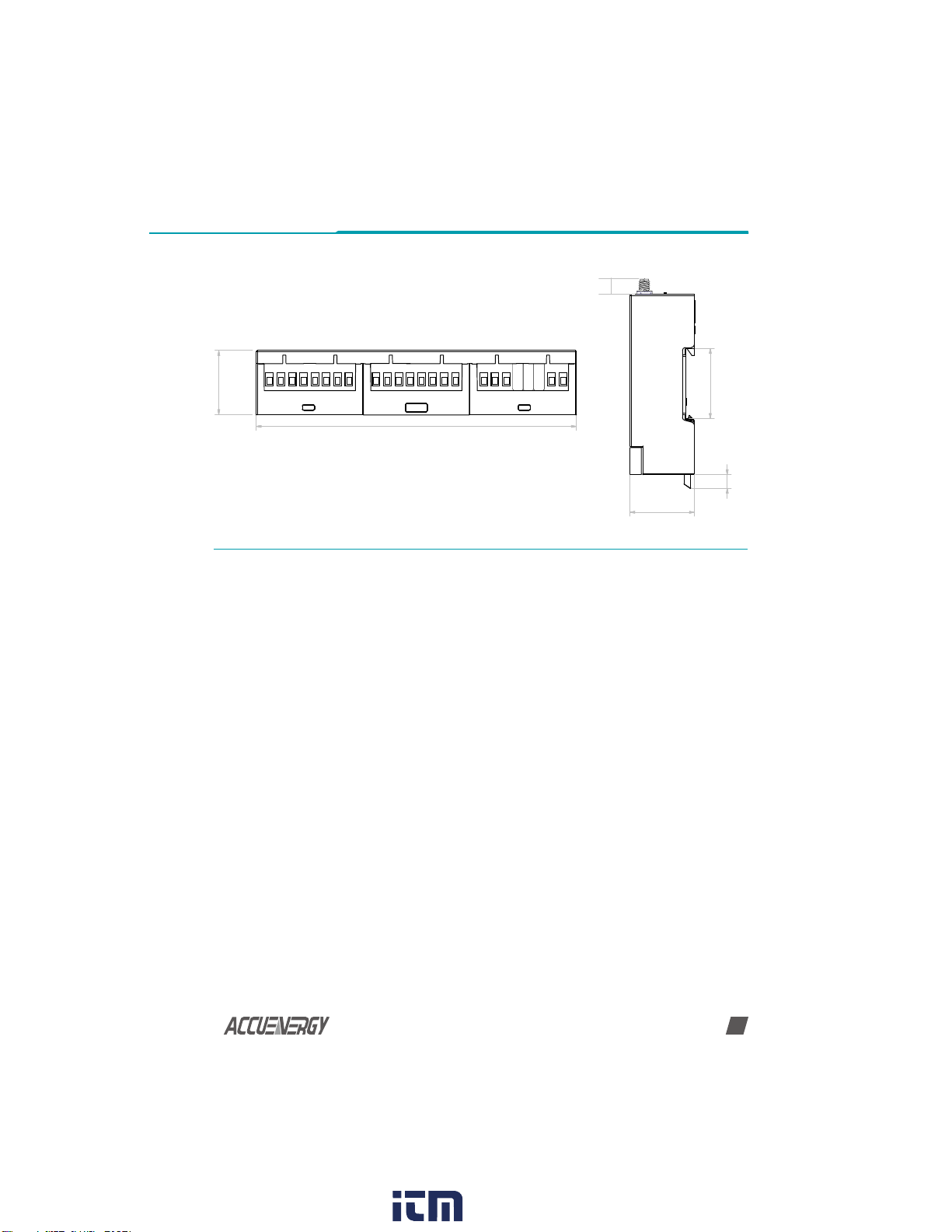
3. Appearance and Dimensions
DATA ACQUSITION SERVER
159.9mm (6.3”)
90mm (3.5”)
10mm
www. .com information@itm.com1.800.561.8187
V: 1.0 Revised: May. 2019
7
Chapter 4: Installation
4. Installation
4.1 Installation Checklist
The following materials are required for the AcuLink 810 installation:
• AcuLink 810 Data Acquisition Server
• Ethernet Connection
• Ethernet Cat 5 Cable (Required for LAN or direct computer to AcuLink 810 connection)
• Power Supply (24V)
• WIFI Antenna
Optional Hardware:
• Additional Modbus RTU devices
• 2 wire Modbus/RS485 connection
LAN Information
• Ethernet 10/100MB connection point (router/switch)
• IP address and subnet mask (Check with system administrator)
• Gateway Address (Check with system administrator)
• DNS server address (Check with system administrator)
159.9mm (6.3”)
32.2mm
(1.27”)
6.8mm
32.2mm
(1.27”)
35mm
10mm
www. .com information@itm.com1.800.561.8187

V: 1.0 Revised: May. 2019
8
Chapter 4: Installation
4.2 Hardware installation
The AcuLink 810 is DIN rail mounted, a standard 35 mm DIN rail can be used.
4.2.1 Powering the unit
• The power supply of the AcuLink 810 is rated for 24Vdc.
DATA ACQUSITION SERVER
+V -V
24Vdc
www. .com information@itm.com1.800.561.8187
Otros manuales para AcuLink 810
1
Tabla de contenidos
Otros manuales de Servidor de AccuEnergy


