ABB SafeRing Manual de usuario

NOPOWSR 5976 GB
1
ABB / PTMV
SafeRing / SafePlus
SF6 insulated ring main unit and compact switchgear
Installation and operating instructions
NOPOWSR 5976 GB
SafeRing / SafePlus
SF6 insulated ring main unit and compact switchgear
Installation and operating instructions
NOPOWSR 5976 GB

NOPOWSR 5976 GB
2ABB / PTMV
SafeRing / SafePlus
SF6 insulated ring main unit and compact switchgear
Installation and operating instructions
Contents
1. General description ........................................................ 3
1.1 Table o locations .............................................................. 4
1.2 Dimensional drawings ....................................................... 5
2. Transport and handling .................................................. 6
2.1 By receiving Inspection ..................................................... 6
2.2 Storage ............................................................................. 6
3. Technical data ................................................................. 7
3.1 Electrical data ................................................................... 7
3.2 Fuse table or modules ..................................................... 8
. Installation ....................................................................... 9
4.1 Cable compartment .......................................................... 10
4.2 Cable connection .............................................................. 11
4.3 Current trans ormers or relay protection .......................... 12
4.4 Gas pressure .................................................................... 13
5. Operation ......................................................................... 13
5.1 Operating conditions ......................................................... 13
5.2 Operation .......................................................................... 14
5.3 Installation and replacement o uses ............................... 15
5.4 Relays ............................................................................... 17
6. Additional equipment ..................................................... 17
6.1 Low-voltage connections auxiliary contacts ..................... 17
6.2 Remote control and monitoring unit .................................. 17
6.3 Capacitive voltage indicator .............................................. 18
6.4 Short circuit indicator ........................................................ 18
6.5 Motor operation ................................................................. 19
6.6 Cable testing ..................................................................... 19
6.7 External busbar ................................................................. 20
6.8 Arc-suppressor .................................................................. 20
6.9 Pressure indicator ............................................................. 20
6.10 Base rame ........................................................................ 20
6.11 Ronis key interlock ............................................................ 20
6.12 Top entry box or low voltage cables ................................ 20
6.13 Low voltage compartment ................................................. 20
7. Maintenance .................................................................... 21
7.1 Control and monitoring the gas ........................................ 21
7.2 Environmental certi ication ................................................ 22

NOPOWSR 5976 GB
3
ABB / PTMV
SafeRing / SafePlus
SF6 insulated ring main unit and compact switchgear
Installation and operating instructions
SafeRing / SafePlus with vacuum circuit-breaker in
compliance with IEC 60056
With this unit the trans ormer will be protected by a vacuum
circuit breaker combined with relays and current trans ormers.
The standard relays are based on digital technology and do not
require an external power supply.
Further in ormation can be ound in the product catalogue or
Sa eRing NOPOWSR 5974 GB and or Sa ePlus NOPOWSP
6004 GB.
Sa eRing is a SF6 insulated ring main unit and Sa ePlus is a
compact switchgear or applications in medium voltage
distribution networks. Sa eRing can be supplied as a 2, 3 or 4-
way standard con igurations with additional equipment
according to customer speci ication. DF, CCF, CCC, CCCF,
CCFF, DV, CCV, CCCC, CCCV, CCVV.
Sa ePlus has a unique lexibility due to its extendibility and the
possible combination o ully modular and semi modular
con igurations. Be - SL - Sv - M - C - De - D - F - V.
Sa eRing and Sa ePlus o ers a sealed stainless steel tank
which contains all the live components and switching unctions.
The trans ormer is protected either by a switch use
combination or a vacuum circuit-breaker.
The units/ modules are delivered rom the actory ready or
installation.
Routine tests are carried out on all units/ modules be ore
dispatch.
No special tools are required or installing the equipment.
Available modules are :
C - Cable switch
F - Switch use disconnector
D- Direct cable connection
De - Direct cable connection with earthing
V - Vacuum circuit breaker
SL - Busbar sectionalizer, load break switch
Busrise needed when SL on right side o SF6 tank
Sv - Busbar sectionalizer, vacuum circuit breaker
Sv always together with busrise (total width=650 mm)
Be - Busbar earthing
M - Metering cubicle
SafeRing / SafePlus with switch fuse combination in
compliance with IEC 60 20.
With this unit the trans ormer will be protected by current-limiting
HV uses in combination with a load break switch. The load
break switch is equipped with a stored spring energy
mechanism which can be tripped by the use striker pin.
1. GENERAL DESCRIPTION
Sa eRing 3 - way unit CCV
Sa ePlus 5 + 1 module with external busbar
Sa ePlus 14 modules

NOPOWSR 5976 GB
4ABB / PTMV
SafeRing / SafePlus
SF6 insulated ring main unit and compact switchgear
Installation and operating instructions
1. Li ting lugs
2. Capacitive voltage indication (additional equipment)
3. Short circuit indicator (additional equipment)
4. Pressure indicator (additional equipment)
5. Legend plate with serial number
6. Mimic diagram
7. Relay protection
8. Blown use indicator
9. Padlock device
10. Cable compartment
11. Test bushings (additional equipment)
12. Ronis key interlock (additional equipment)
13. Circuit breaker
14. Fuse switch disconnector
15. Earthing switch
16. Isolator
17. Circuit breaker open/ emergency stop
18. Circuit breaker close
19. Fuses
1.1 TABLE OF LOCATIONS
NHP 304711

NOPOWSR 5976 GB
5
ABB / PTMV
SafeRing / SafePlus
SF6 insulated ring main unit and compact switchgear
Installation and operating instructions
NHP 102103
1-way 371
2-way 696
3-way 1021
4-way 1346
5-way 1671
Unit mm
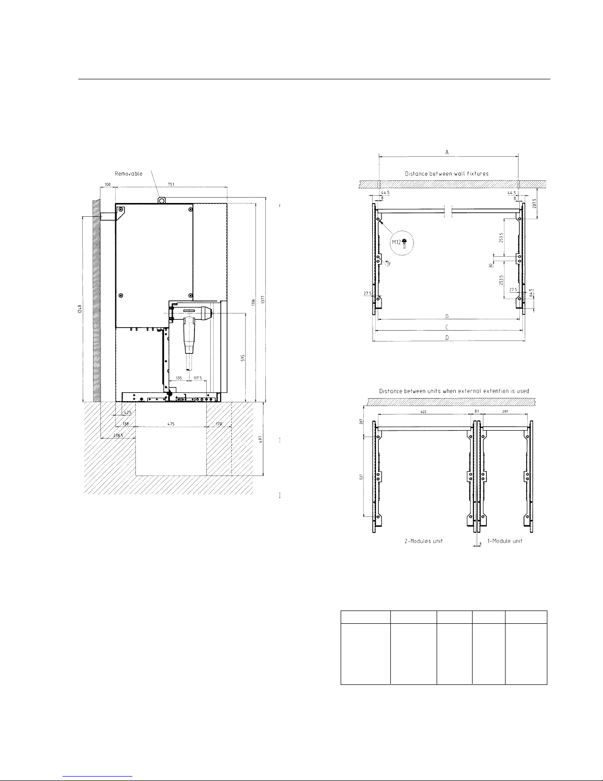
1.2 Dimensional drawings

NOPOWSR 5976 GB
6ABB / PTMV
SafeRing / SafePlus
SF6 insulated ring main unit and compact switchgear
Installation and operating instructions
2. TRANSPORT AND HANDLING
The units are delivered rom the actory ready or installation.
Weight table or standard Sa eRing
2-way DV 252 kg 2-way DF 260 kg
3-way CCV 313 kg 3-way CCF 320 kg
4-way CCCV 403 kg 4-way CCCF 410 kg
4-way CCVV 411 kg 4-way CCFF 430 kg
3-way CCC 300 kg
4-way CCCC 390 kg
Sa ePlus
Standard 1-way 130 kg
2–3 and 4-way as or Sa eRing
5-way approx. between 480–600 kg
M-metering cubicle approx. 250 kg
The weights is without additional equipment
Sa eRing / Sa ePlus is itted with li ting lugs, but can also be
moved on pallets with a orkli t truck.
2.1 BY RECEIVING INSPECTION
Upon receiving the Sa eRing / Sa ePlus please check that the
delivered equipment has not been damaged during transport. I
any such damage has occurred, a claim must be submitted to
the carrier immediately.
A ter unpacking, the ollowing must be checked:
1. Operating handle – 1 piece should be included.
2. Check that the pointer on the pressure indicator is in the
green area.
3. Carry out a unction test on the mechanical parts.
Any aults or omissions must be reported immediately to the
supplier.
2.2 STORAGE
Sa eRing / Sa ePlus must be stored under cover in a dry and
well-ventilated area until it is installed and put into operation.
NHP 407789 NHP 407791
NHP 304311
NHP 408156

NOPOWSR 5976 GB
7
ABB / PTMV
SafeRing / SafePlus
SF6 insulated ring main unit and compact switchgear
Installation and operating instructions
3.1 ELECTRICAL DATA
3. TECHNICAL DATA
C-module F-module V-module
SafeRing Switch Downstream Vacuum circuit
disconnector Earthing switch Switch use earthing switch breaker Earthing switch
Rated voltage kV 12/17,5/24 12/17,5/24 12/17,5/24 12//17,5/24 12/17,5/24 12/17,5/24
Power frequency withstand voltage kV 28/38/50 28/38/50 28/38/50 28/38/50 28/38/50 28/38/50
Impuls withstand voltage kV 95/95/125 95/95/125 95/95/125 95/95/125 95/95/125 95/95/125
Rated current A 630/630/630 see1200/200/200
Breaking capacities:
active load A 630/630/630
closed loop A 630/630/630
o load cable charging A 135/135/135
o load trans ormer A 20/20/20
earth ault A 200/150/150
earth ault cable charging A 115/87/87
short circuit breaking current kA see221/16/16
Making capacity kA 52,5/40/40 52,5/40/40 see212,5/12,5/12,5 52,5/40/40 52,5/40/40
Short time current 1 sec. kA 5/5/5 21/16/16
Short time current 3 sec. kA 21/16/16 21/16/16 21/16/16
C-module F-module V-module
SafePlus Switch Downstream Vacuum circuit
disconnector Earthing switch Switch use earthing switch breaker Earthing switch
Rated voltage kV 12/17,5/24 12/17,5/24 12/17,5/24 12/17,5/24 12/15/17,5/24 12/15/17,5/24
Power frequency withstand voltage kV 28 /38/50 28 /38/50 28 /38/50 28 /38/50 28/38/ 38/50 28 /38/38/50
Impuls withstand voltage kV 95/95/125 95/95/125 95/95/125 95/95/125 95/95/95/125 95/95/95/125
Rated current A 630/630/630 see1630/630/630/630
Breaking capacities:
active load A 630/630/630
closed loop A 630/630/630
o load cable charging A 135/135/135
o load trans ormer A 20/20/20
earth ault A 200/150/150
earth ault cable charging A 115/87/87
short circuit breaking current kA see221/21/16/16
Making capacity kA 62,5/52,5/52,5 62,5/52,5/52,5 see212,5/12,5/12,5 52,5/52,5/40/40 52,5/52,5/40/40
Short time current 1 sec. kA 25/-/- 25/-/- 5/5/5
Short time current 3 sec. kA 21/21/21 21/16/21 21/21/16/16 21/21/16/16
1) Depending on the current rating o the use 2) Limited by High Voltage use links
Sa ering RMU/Sa ePlus CSG is testet according to IEC publications IEC 60056, IEC 60129, IEC 60265, IEC 60298, IEC 60420 and IEC 60694

NOPOWSR 5976 GB
8ABB / PTMV
SafeRing / SafePlus
SF6 insulated ring main unit and compact switchgear
Installation and operating instructions
Ny tabell kommer
Trans ormer rating (kVA): CEF
7,2 kV 12 kV 17,5 kV 24 kV
UN (kV) 25 50 75 100 125 160 200 250 315 400 500 630 800 1000 1250 1600
3 16 25 25 40 40 50 50 80 100 125 160 160
3,3 16 25 25 40 40 50 50 63 80 100 125 160
4,15 10 16 25 25 40 40 50 50 63 80 100 125 160
51016252525404050 50 6380100160160
5,5 616162525254050 50 6380100125160
6 6 16 16 25 25 25 40 40 50 50 80 100 125 160 160
6,6 616162525254040 50 50 6380100125160
10 6 10 10 16 16 25 25 25 40 40 50 50 80 80 125 125
11 6 6 10 16 16 25 25 25 25 40 50 50 63 80 100 125
12 6 6 10 16 16 16 25 25 25 40 40 50 63 80 100 125
13,8 6 6 10 10 16 16 25 25 25 25 40 50 50 63 80 100
15 6 6 10 10 16 16 16 25 25 25 40 40 50 63 80 100
17,5 6 6 6 10 10 16 16 16 25 25 25 40 50 50 63 80
20 6 6 6 10 10 16 16 16 25 25 25 40 40 50 63 63
22 6 6 6 6 10 10 16 16 16 25 25 25 40 50 50 63
24 6 6 6 6 10 10 16 16 16 25 25 25 40 40 50 63
– The table is based on using uses type ABB CEF
– Normal operating conditions with no overload
– Ambient temperature -25°C + 40°C
100%
Trans ormer rating (kVA):
CEF
7,2 kV 12 kV 17,5 kV 24 kV
– The table is based on using uses type ABB CEF
– Normal operating conditions with 20% overload
– Ambient temperature -25°C + 40°C
UN (kV) 25 50 75 100 125 160 200 250 315 400 500 630 800 1000 1250 1600
3 16 25 25 40 40 50 63 80 100 125 160
3,3 16 25 25 40 40 50 63 80 80 100 125
4,15 10 16 25 25 40 40 50 63 80 80 100 125
51016252525404050 63 8080125160
5,5 616162525254050 50 8080100125160
6 6 16 16 25 25 25 40 40 50 63 80 100 125 160
6,6 616162525254040 50 63 8080100125
10 6 10 10 16 16 25 25 25 40 40 50 63 80 80 125
11 6 6 10 16 16 25 25 25 25 40 50 50 80 80 100 125
12 6 6 10 16 16 16 25 25 25 40 40 50 63 80 100 125
13,8 6 6 10 10 16 16 25 25 25 25 40 50 50 80 80 100
15 6 6 10 10 16 16 16 25 25 25 40 40 50 63 80 100
17,5 6 6 6 10 10 16 16 16 25 25 25 40 50 50 63 80
20 6 6 6 10 10 16 16 16 25 25 25 40 40 50 63
22 6 6 6 6 10 10 16 16 16 25 25 25 40 50 50 63
24 6 6 6 6 10 10 16 16 16 25 25 25 40 40 50 63
120%
3.2 FUSE TABLE FOR MODULES
NOPOWSR 5976 GB
9
ABB / PTMV
SafeRing / SafePlus
SF6 insulated ring main unit and compact switchgear
Installation and operating instructions
. INSTALLATION
The base must be lat and itted with anchor bolts in accordance
with the dimensional drawing or the number o modules or
units as appropriate.
223427386
1-way 281 297 336 371
2-way 606 622 661 696
3-way 931 947 986 1021
4-way 1256 1272 1311 1346
5-way 1581 1597 1636 1671
Unit A B C D
NHP 102102

NOPOWSR 5976 GB
10 ABB / PTMV
SafeRing / SafePlus
SF6 insulated ring main unit and compact switchgear
Installation and operating instructions
.1 CABLE COMPARTMENT
Removal o cable cover:
NB!
The cable cover can be supplied with interlocking to earthing
switches. When interlocking is itted, the cable cabinet can only
be accessed when the earthing switch is in the closed position.
4. The panel can be removed by unscrewing A
and B.
2. Removal o ront section.
1. Loosen the screws on the cable cover,
pull out and li t cover o .
3. Front section removed.
A
B
Otros manuales para SafeRing
4
Este manual sirve para los siguientes modelos
1
Tabla de contenidos
Otros manuales de Distribución de energía CA de ABB


